Nissan Sentra Service Manual: Door handle
Front door handle
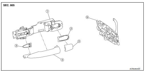
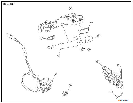
Front door handle : exploded view
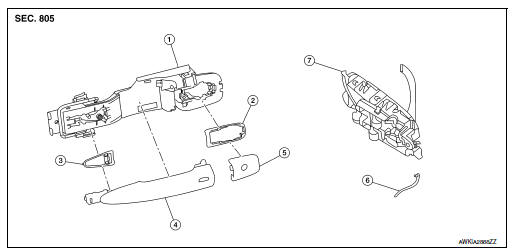
- Outside handle bracket
- Front gasket
- Outside handle
- Intelligent key button
- Door key cylinder rod
- Inside handle assembly
- Rear gasket
Front door handle : removal and installation - inside handle
REMOVAL
- Remove front door finisher. Refer to INT-15, "Removal and Installation".
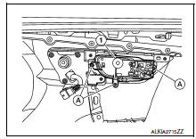
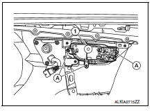
- Remove screws (A) and inside handle assembly (1).
INSTALLATION
Installation is in the reverse order of removal.
CAUTION:
- Check front door lock cables are properly engaged to inside handle.
- After installation, check front door open/close, lock/unlock operation.
Front door handle : removal and installation - outside handle
REMOVAL
- Fully close front door glass.
- Remove front door finisher. Refer to INT-15, "Removal and Installation".
- Remove front door vapor barrier.
- Remove front door glass channel rear.
- Disconnect the harness connectors from the door antenna and door request switch and then remove harness clamp on outside handle bracket.
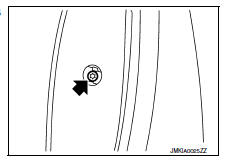
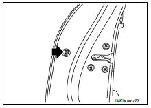
- Remove door side grommet, and loosen screw (

) that retains the front door outside handle bracket.
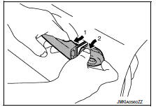
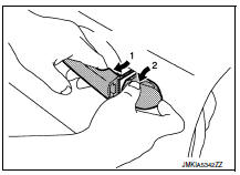
- Reach in to separate door key cylinder rod (LH side) (1) from door key cylinder assembly (LH side) (2).
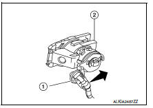
- While pulling (1) outside handle, remove (2) door key cylinder assembly (LH side) or outside handle escutcheon (RH side).
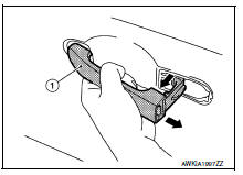
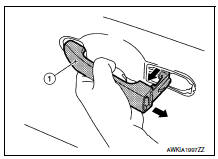
- While pulling outside handle (1), slide toward rear of vehicle to remove outside handle.
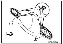
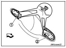
- Remove front gasket (1) and rear gasket (2).
 : Front
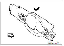
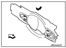
- Slide outside handle bracket toward rear of vehicle to remove.
 : Front
- Disconnect the outside handle cable from the outside handle bracket connection.
INSTALLATION
Installation is in the reverse order of removal.
CAUTION:
- When installing door key cylinder rod on the (LH) front door, be sure to rotate door key cylinder rod holder until a click is felt.
- Check front door lock cable is properly engaged to outside handle bracket.
- After installation, check front door open/close, lock/unlock operation.
Rear door handle
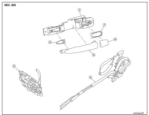
Rear door handle : exploded view
- Outside handle bracket
- Front gasket
- Outside handle
- Outside handle escutcheon
- Inside handle
- Rear gasket
Rear door handle : removal and installation - inside handle
REMOVAL
- Remove rear door finisher. Refer to INT-19, "Removal and Installation".
- Remove screws (A) and inside handle (1).
INSTALLATION
Installation is in the reverse order of removal.
CAUTION:
- Check rear door lock cables are properly engaged to inside handle.
- After installation, check rear door open/close, lock/unlock operation.
Rear door handle : removal and installation - outside handle
REMOVAL
- Fully close rear door glass.
- Remove rear door finisher. Refer to INT-19, "Removal and Installation".
- Remove rear door vapor barrier.
- Remove door side grommet, and loosen screw (
 )that retains
the rear door outside handle bracket.
- While pulling (1) outside handle, remove (2) outside handle escutcheon.
- While pulling outside handle (1), slide toward rear of vehicle to remove outside handle.
- Remove front gasket (1) and rear gasket (2).
 : Front
- Slide outside handle bracket toward rear of vehicle to remove.
 : Front
- Remove clip and disconnect the outside handle cable from the outside handle bracket.
INSTALLATION
Installation in the reverse order of removal.
CAUTION:
- Check rear door lock cable is properly engaged to outside handle bracket.
- After installation, check rear door open/close, lock/unlock operation.
Door loock
FRONT DOOR LOCK
Front door lock : exploded view
- Outside handle bracket
- Front gasket
- Front door handle
- Front door lock assembly
- Door striker
- Door key cylinder rod (driver side)
- Inside handle
- Intelligent Key button
- Outside handle escutcheon
- Rear gasket
Front door lock : removal and installation
CAUTION:
Before servicing, turn ignition switch OFF, disconnect both battery terminals and wait at least three minutes.
REMOVAL
- Remove the front door outside handle. Refer to DLK-173, "FRONT DOOR HANDLE : Removal and Installation - Outside Handle".
- Remove the rear glass run.
- Disconnect the harness connector from the front door lock actuator.
- Remove screws and the front door lock assembly.
INSTALLATION
Installation is in the reverse order of removal.
Tighten front door lock screws to specified torque.
Front door lock screws: 5.8 Nm (0.59 kg-m, 51 in-lb)
CAUTION:
- Do not reuse front door lock assembly screws. Always replace screws with new ones when removed.
- Check front door lock cables are properly engaged to inside handle and outside handle bracket.
- When installing door key cylinder rod on the (LH) front door, be sure to rotate door key cylinder rod holder until a click is felt.
- After installation, check front door open/close, lock/unlock operation.
- Check front door lock assembly for poor lubrication. If necessary apply a suitable multi-purpose grease.
Rear door lock
Rear door lock : exploded view
- Outside handle bracket
- Front gasket
- Inside handle assembly
- Door lock assembly
- Outside handle
- Outside handle escutcheon
- Rear gasket
Rear door lock : removal and installation
REMOVAL
- Remove the rear door outside handle. Refer to DLK-176, "REAR DOOR HANDLE : Removal and Installation - Outside Handle".
- Disconnect the harness connector from the rear door lock actuator.
- Remove the screws and the rear door lock assembly.
INSTALLATION
Installation is in the reverse order of removal.
Tighten rear door lock screws to specified torque.
Rear door lock screws: 5.8 Nm (0.59 kg-m, 51 in-lb)
CAUTION:
- Do not reuse rear door lock assembly screws. Always replace screws with new ones when removed.
- Check rear door lock cables are properly engaged to inside handle and outside handle bracket.
- After installation, check rear door open/close, lock/unlock operation.
- Check rear door lock assembly for poor lubrication. If necessary apply a suitable multi-purpose grease.
 Rear door
Door assembly
DOOR ASSEMBLY : Removal and Installation
CAUTION:
Use two people when removing or installing the rear door assembly
due to its heavy weight.
When removing and installing rear ...
 Trunk lid
Trunk lid assembly
Trunk lid assembly : exploded view
Trunk lid hinge LH/RH
Torsion bar LH/RH
Torsion bar clips
Trunk lid finisher (if equipped)
Emergency release handle
Emergency rel ...
Other materials:
Seat belts
The seat belts can be cleaned by wiping them
with a sponge dampened in a mild soap solution.
Allow the belts to dry completely in the shade
before using them. See “Seat belt maintenance”
in the “Safety – Seats, seat belts and supplemental
restraint system” section of this manual.
...
FM/AM radio with compact disc (CD) player (if so equipped)
CD eject button
CD insert slot
SCAN button
DISP button
RPT/RDM button
TUNE/FOLDER knob / MENU button
AUX IN jack
AUX button
CD button
AM button
FM button
VOL (volume) control knob
/ (power) button
Station select (1 - 6) buttons
TRACK button
SEEK button
For ...
Bcm branch line circuit
Diagnosis Procedure
1.Check connector
Turn the ignition switch off.
Disconnect the battery cable from the negative terminal.
Check the terminals and connectors of the BCM for damage, bend and loose
connection (unit side and
connector side).
Is the inspection result normal?
YES > ...
