Nissan Sentra Service Manual: Rear door
Door assembly
DOOR ASSEMBLY : Removal and Installation
CAUTION:
- Use two people when removing or installing the rear door assembly due to its heavy weight.
- When removing and installing rear door assembly, support rear door with a suitable tool.
REMOVAL
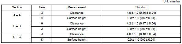
- Remove rear door assembly harness grommet (LH) (1) then pull out door harness from body (2).
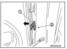
- Disconnect the harness connector (A) from the door harness.
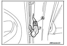
- Remove the check link bolt from the body.
- Remove rear door assembly hinge nuts (A) (door side) and the door assembly (1).
INSTALLATION
Installation is in the reverse order of removal.
Tighten rear door hinge nuts (door side) to specified torque.
CAUTION:
- After installation, check rear door open/close, lock/unlock operation.
- After installation, perform the rear door adjustment procedure. Refer to DLK-169, "DOOR ASSEMBLY : Adjustment".
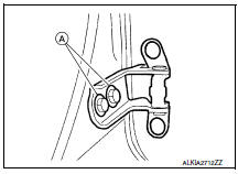
DOOR ASSEMBLY : Adjustment
ADJUSTMENT
- Front fender
- Door assembly
- Rear door assembly
- Body side outer
- Rear door striker
- Rear door upper hinge
- Rear door lower hinge
- Rear door striker screws
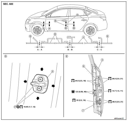
Check the clearance and surface height between rear door and each part by visual inspection and tactile feel.
If the clearance and the surface height are out of specification, adjust them according to the adjustment procedure.
LONGITUDINAL CLEARANCE
- Remove the center pillar upper finisher. Refer to INT-28, "CENTER PILLAR UPPER FINISHER : Removal and Installation" .
- Loosen the rear door upper hinge nuts.
- Loosen the rear door lower hinge bolts.
- Move the rear door forward or backward as necessary until within specifications provided.
- Tighten the lower hinge bolts to specification.
Rear door lower hinge bolts 22 NВ·m (2.2 kg-m, 16 ft-lb)
- Tighten the upper hinge nuts to specification.
Rear door upper hinge nuts 22 NВ·m (2.2 kg-m, 16 ft-lb)
- Install the center pillar upper finisher. Refer to INT-28, "CENTER PILLAR UPPER FINISHER : Removal and Installation".
SURFACE HEIGHT ADJUSTMENT
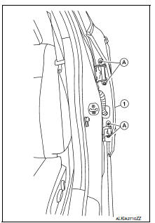
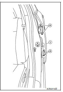
- Loosen the rear door hinge nuts (door side) (A).
- Move the top and/or the bottom of the rear door (1) in or out as necessary until it is within specifications provided.
- Tighten the rear door hinge nuts (door side) (A) to specification.
Rear door nuts 28.0 NВ·m (2.9 kg-m, 21 ft-lb)
CAUTION:
- Check rear door hinge rotating point for poor lubrication. If necessary, apply a suitable multi-purpose grease.
- After adjusting, apply touch-up paint (body color) to the head of rear door assembly hinge bolts and nuts.
- If the clearance measurements cannot be corrected by adjusting the
rear door, adjust the front door.
Refer to DLK-164, "DOOR ASSEMBLY : Adjustment".
DOOR STRIKER ADJUSTMENT
Adjust rear door assembly striker so that it becomes parallel with door lock insertion direction.
Door hinge
Door hinge : removal and installation
CAUTION:
- Use two people when removing or installing rear door assembly due to its heavy weight.
- When removing and installing rear door assembly, support door using a suitable tool.
REMOVAL
- Remove rear door assembly. Refer to DLK-168, "DOOR ASSEMBLY : Removal and Installation".
- Remove center pillar upper finisher (upper hinge only). Refer to INT-28, "CENTER PILLAR UPPER FINISHER : Removal and Installation".
- Remove rear door assembly upper hinge nuts (A) and remove.
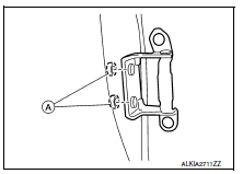
- Remove rear door assembly lower hinge bolts (A) and remove.
INSTALLATION
Installation is in the reverse order of removal.
Tighten rear door assembly hinge nuts and bolts to specified torque.Refer to DLK-169, "DOOR ASSEMBLY : Adjustment"
CAUTION:
- Apply anticorrosive agent onto the hinge mating surface.
- After installation, check rear door open/close, lock/unlock operation.
- After installation, perform the rear door adjustment procedure. Refer to DLK-169, "DOOR ASSEMBLY : Adjustment".
Door check link
DOOR CHECK LINK : Removal and Installation
REMOVAL
- Fully close the rear door glass.
- Remove rear door speaker (if equipped). Refer to AV-61, "Removal and Installation" (BASE AUDIO), AV- 206, "Removal and Installation" (DISPLAY AUDIO WITH BOSE), AV-125, "Removal and Installation" (DISPLAY AUDIO WITHOUT BOSE) AV-409, "Removal and Installation" (NAVIGATION WITH BOSE) and AV-301, "Removal and Installation" (NAVIGATION WITHOUT BOSE).
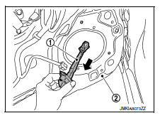
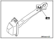
- Remove door check link bolt from body.
- Remove door check link bolts on door panel.
- Remove door check link (1) through the hole in door panel (2).
INSTALLATION
Installation is in the reverse order of removal.
CAUTION:
- After installation, check rear door open/close, lock/unlock operation.
- Check rear door check link rotating point for poor lubrication.
If necessary, apply a suitable multi-purpose grease.
 Front door
Door assembly
Door assembly : removal and installation
CAUTION:
Use two people when removing or installing the front door assembly
due to its heavy weight.
When removing and installing fro ...
 Door handle
Front door handle
Front door handle : exploded view
Outside handle bracket
Front gasket
Outside handle
Intelligent key button
Door key cylinder rod
Inside handle assembly
Rear ga ...
Other materials:
SPORT mode switch
Adjusts the throttle sensitivity and transmission
points (CVT only) to enhance performance. Press
the SPORT button on the instrument panel to
activate. The SPORT mode indicator light (on the
speedometer) will illuminate. The SPORT mode
indicator light will remain lit while the mode is
acti ...
Starting the engine
Apply the parking brake.
CVT model:
Move the shift lever to P (Park) or N (Neutral).
P (Park) is recommended.
The shift lever cannot be moved out of
P (Park) and into any of the other gear
positions if the ignition switch is
turned to the OFF position or if the key
is removed from th ...
Steering wheel
Exploded View
Driver air bag module
Steering wheel
Steering column assembly
Removal and Installation
REMOVAL
NOTE:
When reconnecting spiral cable, fix cable with a tape so that
fixing case and rotating part keep aligned. This
will omit neutral position alignment procedu ...
