Nissan Sentra Service Manual: Steering wheel
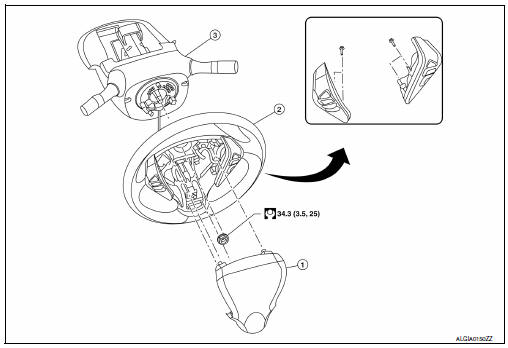
Exploded View
-
Driver air bag module
-
Steering wheel
-
Steering column assembly
Removal and Installation
REMOVAL
NOTE:
When reconnecting spiral cable, fix cable with a tape so that fixing case and rotating part keep aligned. This will omit neutral position alignment procedure during spiral cable installation.
-
Set steering wheel to the straight-ahead position.
-
Remove driver air bag module. Refer to SR-12, "Removal and Installation".
-
Disconnect harness connectors from clipping locations.
-
Remove steering wheel lock nut.
-
Remove steering wheel using suitable tool (A).
NOTE:
Put paint marks on the steering wheel and the column shaft head for supporting accurate positioning during the installation procedure.
Installation is in the reverse order of removal.
-
Check the spiral cable neutral position after replacing or rotating spiral cable. Refer to SR-16, "Removal and Installation".
CAUTION:
-
Do not twist spiral cable excessively after it becomes tight. (Twisting may cause the cable to be torn off.)
-
Do not reuse steering wheel lock nut.

 Steering column
Exploded View
Steering column assembly
Slide plates
lower shaft assembly
Removal and Installation
REMOVAL
CAUTION:
While removing the steering column assembly, do not ...
Other materials:
Rear power window motor
Removal and Installation
REMOVAL
Remove the rear door glass regulator (1). Refer to GW-21,
"Removal and Installation"
Remove the screws and the rear power window motor (2).
INSTALLATION
Installation is in the reverse order of removal. ...
Moonroof (if so equipped)
Power moonroof
The moonroof will only operate when the ignition
switch is placed in the ON position. The power
moonroof is operational for a period of time, even
if the ignition switch is placed in the ACC or OFF
position. If the driver’s door or the front passenger’s
door is opened du ...
Fuel efficient driving tips
Follow these easy-to-use Fuel Efficient Driving
Tips to help you achieve the most fuel economy
from your vehicle.
Use Smooth Accelerator and Brake
Pedal Application
Avoid rapid starts and stops
Use smooth, gentle accelerator and
brake application whenever possible
Maintain consta ...
