Nissan Sentra Service Manual: Steering column
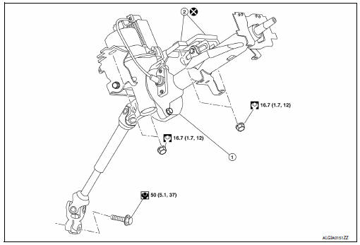
Exploded View
-
Steering column assembly
-
Slide plates
-
lower shaft assembly
Removal and Installation
REMOVAL
CAUTION:
-
While removing the steering column assembly, do not unlock the tilt lever.
-
Do not impact on the axis when removing steering column assembly.
-
Be careful when removing steering column assembly from the vehicle because it is heavy.
-
Keep steering column assembly away from magnetic sources.
-
Do not disassemble steering column assembly, it is all one piece.
-
While removing the steering column assembly, do not move the steering gear assembly.
-
When removing the steering column assembly, be careful not to allow the lower shaft assembly to turn.
-
Set steering wheel to the straight-ahead position.
-
Place the tilt to the lowest level.
CAUTION:
Securely lock the tilt lever.
-
Remove instrument lower panel LH. Refer to IP-21, "Removal and Installation".
-
Remove driver air bag module. Refer to SR-12, "Removal and Installation".
-
Remove steering wheel. Refer to ST-10, "Removal and Installation".
-
Remove steering column cover. Refer to IP-16, "Removal and Installation".
-
Remove spiral cable. Refer to SR-16, "Removal and Installation".
-
Remove combination switch.
-
Disconnect key interlock cable (if equipped). Refer to TM-260, "Removal and Installation".
-
Remove hole cover (1).
-
Lower shaft assembly (2).
-
Remove lower side bolt of lower shaft assembly.
-
Disconnect each harness connector and harness clips installed to steering column assembly.
-
Disconnect EPS control unit harness connectors.
-
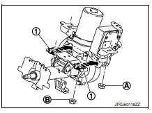
Remove the steering column assembly nuts.
CAUTION:
When removing the steering column assembly nuts, be careful not to drop the steering column assembly.
-
Remove the steering column.
-
Remove EPS control unit. Refer to STC-39, "Removal and Installation".
INSTALLATION
CAUTION:
-
Do not impact on the axis when removing steering column assembly.
-
When installing the steering column cover, check that the vehicle harness is not stuck in the cover.
Installation is in the reverse order of removal.
-
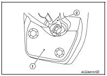
After tightening nut (A) of the steering column assembly, press in slide plate (outer and inner) (1) to tighten nut (B).
CAUTION:
-
Do not reuse slide plate.
-
The slide plate must be securely pressed in before tightening the nut of slide plate.
Lower shaft bolt is directional. Refer to ST-12, "Exploded View".
CAUTION:
Do not reuse lower shaft assembly bolt.
-
After installing steering column assembly, perform self-diagnosis with CONSULT to ensure correct operation.
Refer to STC-10, "CONSULT Function".
-
Perform inspection after installation. Refer to ST-7, "Inspection".
 Steering wheel
Exploded View
Driver air bag module
Steering wheel
Steering column assembly
Removal and Installation
REMOVAL
NOTE:
When reconnecting spiral cable, fix cable with a tape so t ...
 Steering gear and linkage
Exploded View
REMOVAL
Steering gear assembly
Front suspension member
Front
Removal and Installation
REMOVAL
Set steering wheel to the straight-ahead position.
Remove ...
Other materials:
The fuel gauge indicator does not operate
Description
Fuel gauge will not indicate from a certain position.
Diagnosis procedure
1.CHECK FUEL LEVEL SENSOR SIGNAL CIRCUIT
Check the fuel level sensor signal circuit. Refer to MWI-58, "Diagnosis
Procedure".
Is the inspection result normal?
YES >> GO TO 2.
NO >> ...
Unit disassembly and assembly
Front coil spring and strut
Exploded View
Piston rod lock nut
Strut mount insulator
Strut mount bearing
Bound bumper
Coil spring
Lower rubber seat
Strut
Steering knuckle
Front
Disassembly and Assembly
DISASSEMBLY
CAUTION:
Do not damage the piston rod when removing comp ...
Event Data Recorders (EDR)
This vehicle is equipped with an Event Data Recorder
(EDR). The main purpose of an EDR is to
record, in certain crash or near crash-like situations,
such as an air bag deployment or hitting a
road obstacle, data that will assist in understanding
how a vehicle’s systems performed. The EDR
is ...
