Nissan Sentra Service Manual: Steering gear and linkage
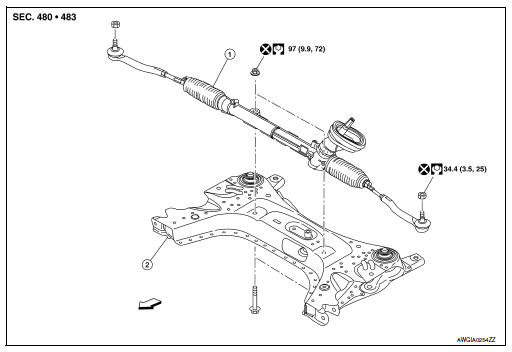
Exploded View
REMOVAL
-
Steering gear assembly
-
Front suspension member
 Front
Front
Removal and Installation
REMOVAL
-
Set steering wheel to the straight-ahead position.
-
Remove floor cover (1).
-
Lower shaft assembly (2).
-
Remove the lower shaft assembly bolt and position the lower shaft assembly out of the way. Refer to ST- 12, "Removal and Installation".
CAUTION:
-
Spiral cable may be cut if steering wheel turns while separating steering column assembly and steering gear assembly. Always fix the steering wheel using string to avoid turning.
-
Place a matching mark on both intermediate shaft and steering gear assembly before removing intermediate shaft.
-
Remove wheels and tires using power tool. Refer to WT-47, "Adjustment".
-
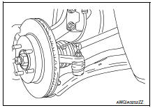
Remove steering outer socket from steering knuckle so as not to damage ball joint boot using Tool.
Tool number : HT72520000 (J-25730-A)
CAUTION:
Temporarily tighten the nut to prevent damage to threads and to prevent the Tool from a sudden drop.
-
Remove front suspension member. Refer to FSU-16, "Removal and Installation".
-
Remove steering gear assembly from front suspension member.
INSTALLATION
Installation is in the reverse order of removal.
CAUTION:
Spiral cable may be cut if steering wheel turns while separating steering column assembly and steering gear assembly. Always fix the steering wheel using string to avoid turning.
-
Perform final tightening of nuts and bolts on each part under unladen conditions with tires on level ground when removing steering gear assembly.
-
Check wheel alignment. Refer to FSU-7, "Adjustment".
-
Rotate steering wheel to check for decentered condition, binding, noise or excessive steering effort.
-
Do not reuse steering outer socket nut and steering gear assembly nut.
-
Perform neutral position steering angle adjustment. Refer to BRC-54, "Work Procedure".
 Steering column
Exploded View
Steering column assembly
Slide plates
lower shaft assembly
Removal and Installation
REMOVAL
CAUTION:
While removing the steering column assembly, do not ...
 Unit disassembly and assembly
Steering gear and linkage
Exploded View
Outer socket
Boot clamp (small diameter)
Boot
Boot clamp (large diameter)
Inner socket
Gear housing assembly
Disassembl ...
Other materials:
Precautions for Suspension
When installing rubber bushings, the final tightening must be carried
out under unladen conditions with tires
on ground. Spilled oil might shorten the life of rubber bushings. Be sure to
wipe off any spilled oil.
Unladen conditions mean that fuel, engine coolant and lubricant are
...
Strg branch line circuit
Diagnosis procedure
1.Check connector
Turn the ignition switch off.
Disconnect the battery cable from the negative terminal.
Check the terminals and connectors of the steering angle sensor for
damage, bend and loose connection
(unit side and connector side).
Is the inspection result ...
Inside mirror
Exploded view
Manual mirror
Windshield glass
Inside mirror base
Inside mirror assembly
Auto anti-dazzle mirror
Windshield glass
Inside mirror base
Harness connector
Mirror screw
Inside mirror assembly
Inside mirror cover
Removal and installation
Manual mirror
...
