Nissan Sentra Service Manual: Strg branch line circuit
Diagnosis procedure
1.Check connector
- Turn the ignition switch off.
- Disconnect the battery cable from the negative terminal.
- Check the terminals and connectors of the steering angle sensor for damage, bend and loose connection (unit side and connector side).
Is the inspection result normal? YES >> GO TO 2.
NO >> Repair the terminal and connector.
2.Check harness for open circuit
- Disconnect the connector of steering angle sensor.
- Check the resistance between the steering angle sensor harness connector terminals.
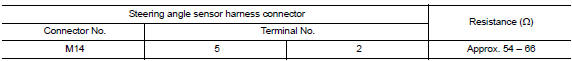
Is the measurement value within the specification? YES >> GO TO 3.
NO >> Repair the steering angle sensor branch line.
3.Check power supply and ground circuit
Check the power supply and the ground circuit of the steering angle sensor. Refer to BRC-44, "Wiring Diagram".
Is the inspection result normal? YES (Present error)>>Replace the steering angle sensor. Refer to BRC-113, "Removal and Installation".
YES (Past error)>>Error was detected in the steering angle sensor branch line.
NO >> Repair the power supply and the ground circuit.
 M&A branch line circuit
Diagnosis procedure
1.Check connector
Turn the ignition switch off.
Disconnect the battery cable from the negative terminal.
Check the terminals and connectors of the combination meter for da ...
 Av branch line circuit
Diagnosis Procedure
1.Check connector
Turn the ignition switch off.
Disconnect the battery cable from the negative terminal.
Check the terminals and connectors of the av control unit for dama ...
Other materials:
Reporting safety defects
For USA
If you believe that your vehicle has a defect
which could cause a crash or could
cause injury or death, you should immediately
inform the National Highway Traffic
Safety Administration (NHTSA) in addition
to notifying NISSAN.
If NHTSA receives similar complaints, it
may open an inv ...
Symptom diagnosis
The sport mode indicator lamp does not turn on
Description
The sport mode indicator lamp does not turn on when the sport mode switch is
operated.
Diagnosis procedure
1.Perform combination meter on board diagnosis
Perform combination meter on board diagnosis. Refer to mwi-16, "descriptio ...
Mixture ratio self-learning value
clear
Description
This describes how to erase the mixture ratio self-learning value. For the
actual procedure, follow the instructions
in “Diagnosis Procedure”.
Work Procedure
1.START
With CONSULT
Start engine and warm it up to normal operating temperature.
Select “SELF-LEARNI ...
