Nissan Sentra Service Manual: Heating and cooling unit assembly
Exploded view
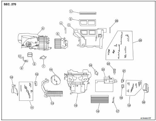
With air conditioning
- Defroster seal
- Center ventilator seal
- Upper distribution module
- Side ventilator seal (LH)
- Blower motor
- Blower unit
- Intake door motor
- Power transistor
- Power transistor wiring harness
- Front floor duct (lh)
- Vent and defroster linkage
- Mode door motor
- Heater core
- Heater core pipes grommet
- Heating and cooling unit
- In-cabin microfilter
- In-cabin microfilter cover
- Air mix door motor (lh) (automatic a/c only)
- Vent and defroster linkage
- Front floor duct (rh)
- Air mix door motor (RH)
- Expansion valve
- Evaporator
- Aspirator (automatic a/c only)
- Vent and defroster linkage
- Side ventilator seal (rh)
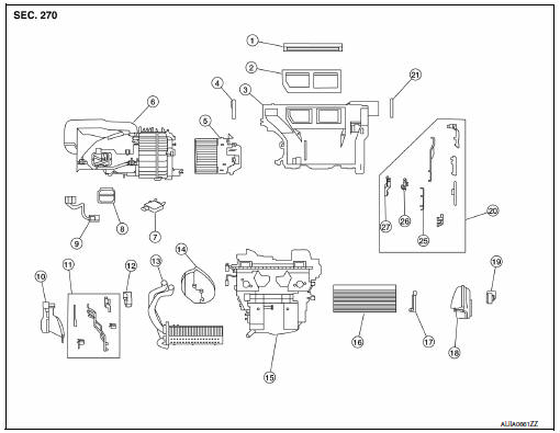
Without air conditioning
- Defroster seal
- Center ventilator seal
- Upper distribution module
- Side ventilator seal (lh)
- Blower motor
- Blower unit
- Intake door motor
- Power transistor
- Power transistor wiring harness
- Front floor duct (LH)
- Vent and defroster linkage
- Mode door motor
- Heater core
- Heater core pipes grommet
- Heating and cooling unit
- In-cabin microfilter
- In-cabin microfilter cover
- Front floor duct (RH)
- Air mix door motor
- Vent and defroster linkage
- Side ventilator seal (RH)
Heating and cooling unit assembly
Heating and cooling unit assembly : removal and installation
NOTE:
When removing components such as hoses, lines/tubes, etc., cap or plug openings to prevent fluid from spilling.
REMOVAL
- Discharge the refrigerant. Refer to HA-23, "Recycle Refrigerant".
- Drain the cooling system. Refer to CO-12, "Changing Engine Coolant".
- Remove the instrument panel assembly. Refer to IP-14, "Removal and Installation".
- Remove the steering column. Refer to ST-12, "Removal and Installation".
- Remove the center console. Refer to IP-17, "Removal and Installation".
- Remove the wiper drive assembly. Refer to WW-62, "Removal and Installation".
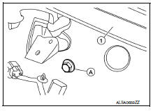
- Remove the steering member bolt (A).
(1): Windshield glass
NOTE:
The steering member bolt (A) can be found near the drivers side cowl area in the engine compartment.
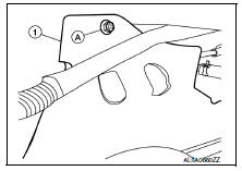
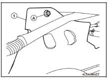
- Remove the push nut (A) from the expansion valve insulator (1) and reposition.
- Remove the bolt (A) that retains the low-pressure flexible hose and high-pressure pipe to the expansion valve.
CAUTION:
Cap or wrap the joint of the pipe with suitable material such as vinyl tape to avoid the entry of air.
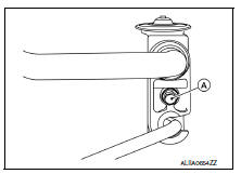
- Disconnect the low-pressure pipe and high-pressure pipe from the expansion valve.
- Disconnect the heater hoses from the heater core pipes.
- Remove the remaining steering member bolts.
- Disconnect the harness connectors from the heating and cooling unit assembly and steering member.
- Remove the heating and cooling unit assembly and steering member as an assembly from the vehicle.
- Separate the heating and cooling unit assembly from the steering member.
INSTALLATION
Installation is in the reverse order of removal.
CAUTION:
- Do not reuse O-rings.
- Apply A/C oil to new O-rings for installation.
- After charging refrigerant, check for leaks. Refer to HA-21, "Leak Test".
Heater core
Heater core : removal and installation
REMOVAL
The heater core is not serviced separately and must be replaced with the heating and cooling unit assembly.
Refer to HA-43, "HEATING AND COOLING UNIT ASSEMBLY : Removal and Installation".
Evaporator
Evaporator : removal and installation
REMOVAL
The evaporator is not serviced separately and must be replaced with the heating and cooling unit assembly.
Refer to HA-45, "EVAPORATOR : Removal and Installation".
Expansion valve
Expansion valve : removal and installation
REMOVAL
- Discharge the refrigerant. Refer to HA-23, "Recycle Refrigerant".
- Remove the push nut (A) from the expansion valve insulator (1) and reposition.
- Remove the bolt (A) that retains the low-pressure flexible hose and high-pressure pipe to the expansion valve.
- Disconnect the low-pressure pipe and high-pressure pipe from the expansion valve.
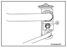
- Remove the expansion valve bolts.
- Remove the expansion valve.
INSTALLATION
Installation is in the reverse order of removal.
CAUTION:
- Do not reuse O-rings.
- Apply A/C oil to the new expansion valve O-rings for installation.
- After charging refrigerant, check for leaks. Refer to HA-21, "Leak Test".
 Condenser
Exploded view
Core support upper cover
High-pressure pipe
High-pressure flexible hose
Refrigerant pressure sensor
Condenser and liquid tank assembly
Core support upper
Front
Conde ...
 Service data and specifications (SDS)
Service Data and Specification (SDS)
COMPRESSOR
OIL
REFRIGERANT
...
Other materials:
Precautions for drive shaft
Observe the following precautions when disassembling and assembling drive
shaft.
Do not disassemble joint sub-assembly because it is non-overhaul parts.
Perform work in a location which is as dust-free as possible.
Clean the parts, before disassembling and assembling.
Prevent the entry o ...
Uniform tire quality grading
DOT (Department of Transportation) Quality
Grades: All passenger car tires must conform to
federal safety requirements in addition to these
grades.
Quality grades can be found where applicable on
the tire sidewall between tread shoulder and
maximum section width. For example:
Treadwear 200 ...
Precaution
Precaution for Supplemental Restraint System (SRS) "AIR BAG" and "SEAT BELT
PRE-TENSIONER"
The supplemental restraint system such as “air bag” and “seat belt pre-tensioner”,
used along
with a front seat belt, helps to reduce the risk or severity of injur ...
