Nissan Sentra Service Manual: Condenser
Exploded view
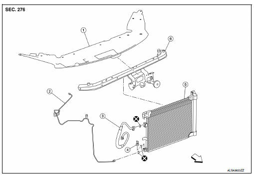
- Core support upper cover
- High-pressure pipe
- High-pressure flexible hose
- Refrigerant pressure sensor
- Condenser and liquid tank assembly
- Core support upper
 Front
Front
Condenser
Condenser : removal and installation
REMOVAL
- Discharge the refrigerant. Refer to HA-23, "Recycle Refrigerant".
- Reposition the hood lock assembly. Refer to DLK-154, "HOOD LOCK CONTROL : Exploded View".
NOTE:
Disconnection of the hood release cable is not necessary.
- Remove the core support upper. Refer to HA-39, "Exploded View".
- Remove the front grille. Refer to EXT-23, "Removal and Installation".
- Disconnect the harness connector from the refrigerant pressure sensor.
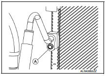
- Remove the bolt (A) that retains the high-pressure flexible hose to the condenser, then disconnect the high-pressure flexible hose from the condenser and liquid tank assembly.
CAUTION:
Cap or wrap the joint of the hose with suitable material such as vinyl tape to avoid the entry of air.
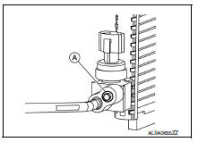
- Remove the bolt (A) that retains the high-pressure pipe to the condenser, then disconnect the high-pressure pipe from the condenser and liquid tank assembly.
- Remove the condenser and liquid tank assembly.
INSTALLATION
Installation is in the reverse order of removal.
CAUTION:
- Do not reuse O-rings.
- Apply A/C oil to the O-rings of the condenser for installation.
- After charging refrigerant, check for leaks. Refer to HA-21, "Leak Test".
Refrigerant pressure sensor
Refrigerant pressure sensor : removal and installation
REMOVAL
- Discharge the refrigerant. Refer to HA-23, "Recycle Refrigerant".
- Reposition the hood lock assembly. Refer to DLK-154, "HOOD LOCK CONTROL : Exploded View".
NOTE:
Disconnection of the hood release cable is not necessary.
- Remove the core support upper. Refer to HA-39, "Exploded View".
- Disconnect the harness connector from the refrigerant pressure sensor.
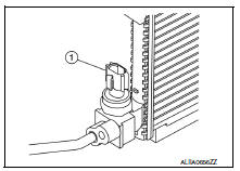
- Remove the refrigerant pressure sensor (1) from the liquid tank on the condenser.
CAUTION:
Do not damage the condenser fins.
INSTALLATION
Installation is in the reverse order of removal.
CAUTION:
- Do not reuse the O-ring.
- Apply A/C compressor oil to the new O-ring for installation.
- After charging refrigerant, check for leaks. Refer to HA-21, "Leak Test".
 Cooler pipe and hose
Exploded view
High-pressure service port
High-pressure pipe
Expansion valve
Low-pressure service port
Low-pressure flexible hose
Compressor
Refrigerant pressure sensor
Condenser ...
 Heating and cooling unit assembly
Exploded view
With air conditioning
Defroster seal
Center ventilator seal
Upper distribution module
Side ventilator seal (LH)
Blower motor
Blower unit
Intake door motor
Power tr ...
Other materials:
How to use the touch-screen
CAUTION
The glass display screen may break if it
is hit with a hard or sharp object. If the
glass screen breaks, do not touch it.
Doing so could result in an injury.
To clean the display, never use a rough
cloth, alcohol, benzine, thinner or any
kind of solvent or paper towel with a
chemic ...
Front wiper motor lo circuit
Component function check
1. Check front wiper lo operation
Ipdm e/r auto active test
Start ipdm e/r auto active test. Refer to pcs-9, "diagnosis description"
(with intelligent key system) or
pcs-37, "diagnosis description" (without intelligent key system).
Check tha ...
Precaution for Work
When removing or disassembling each component, be careful not to damage
or deform it. If a component
may be subject to interference, be sure to protect it with a shop cloth.
When removing (disengaging) components with a screwdriver or similar
tool, be sure to wrap the component
with a ...
