Nissan Sentra Service Manual: System description
Component parts
Nissan vehicle immobilizer system-nats
Nissan vehicle immobilizer systemnats : component parts location
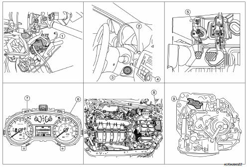
- Bcm (view with instrument panel removed)
- Dongle unit (canada only) (behind instrument panel lh)
- Ignition switch
- Nats antenna amp.
(Inside steering column)
- Clutch interlock switch (M/T models)
- Combination meter
- Security indicator lamp
- Ipdm e/r
- Transmission range switch (cvt models)
Nissan vehicle immobilizer systemnats : component description
| Item | Function |
| Bcm | Verifies the received signal from the ignition key id, then informs ecm whether to allow engine start. |
| Transmission range switch (cvt models) | Detects whether the shift lever is in park. |
| Clutch interlock switch (m/t models) | Detects whether the clutch pedal is depressed. |
| Dongle unit (canada only) | Sends id verification signal to the bcm. |
| Starter relay | Supplies battery voltage to the starter motor when enabled. |
| Nats antenna amp. | Detects the ignition key presence in the ignition key cylinder. |
| Security indicator | Indicates the status of the security system. |
| Ipdm e/r | Supplies battery voltage from integrated starter relay to the starter motor. |
Vehicle security system
Vehicle security system : component parts location
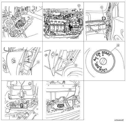
- Bcm (view with instrument panel removed)
- Ipdm e/r
- Remote keyless entry receiver (view with instrument panel removed)
- Front door switch lh (rh similar)
- Rear door switch lh (rh similar)
- Key switch
- Horn relay
- Horn
Vehicle security system : component description
| Item | Function |
| Bcm | Controls the door lock function. |
| Door lock and unlock switch | Input lock or unlock signal to bcm. |
| Door switch | Input door open/close condition to bcm. |
| Key switch | Input key switch condition to BCM. |
| Remote keyless entry receiver | Receives lock/unlock signal from the keyfob, and then transmits to bcm. |
| Key switch | Input key switch on/off condition to bcm. |
| Horn | Provides audible warning in panic mode. |
System
Nissan vehicle immobilizer system-nats
Nissan vehicle immobilizer systemnats : system diagram
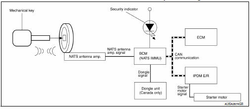
Nissan vehicle immobilizer systemnats : system description
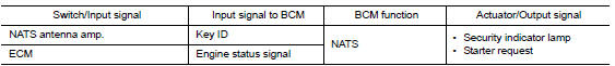
Input/output signal chart
Bcm
System description
NATS (Nissan Anti-Theft System) has the following immobilizer functions:
- Engine immobilizer shows high anti-theft performance to prevent engine from starting by anyone other than the owner.
- Only a key with key id registered in bcm and ecm can start engine, and shows high anti-theft performance to prevent key from being copied or stolen.
- Security indicator always flashes with mechanical key removed condition (key switch: off)
- Therefore, nats warns outsiders that the vehicle is equipped with the anti-theft system.
- If system detects malfunction, security indicator illuminates when ignition switch is turned to on position.
- If the owner requires, ignition key id or mechanical key id can be registered for up to 5 keys.
- During trouble diagnosis or when the following parts have been replaced, and if ignition key is added, registration* 1 is required.
*1: All keys kept by the owner of the vehicle should be registered with mechanical key.
- ECM
- BCM
- Ignition key
- Remote keyless entry receiver
- NATS trouble diagnosis, system initialization and additional registration of other mechanical key IDs must be carried out using CONSULT.
- When NATS initialization has been completed, the ID of the inserted mechanical key or mechanical key IDs can be carried out.
- Possible symptom of NATS malfunction is “Engine cannot start”. Identify the possible causes according to “Work Flow”, Refer to SEC-171, "Work Flow".
- If ECM other than Genuine NISSAN is installed, the engine cannot be started. For ECM replacement procedure, refer to EC-485, "Removal and Installation".
PRECAUTIONS FOR KEY REGISTRATION
- The key registration is a procedure that erases the current NATS ID
once, and then re-registers a new ID.
Therefore the registered key is necessary for this procedure. Before starting the registration procedure, collect all registered Keys from the customer.
- The NATS ID registration is the procedure that registers the ID stored
into the transponder (integrated in
mechanical key) to BCM.
The key ID registration is the procedure that registers the ID to the BCM.
- When performing the key system registration only, the engine cannot be started by inserting the key into the key cylinder. When performing the NATS registration only, the engine cannot be started by using the ignition key.
SECURITY INDICATOR
- Always flashes with ignition key in the OFF position.
MAINTENANCE INFORMATION
CAUTION:
It is necessary to perform NATS ID registration when replacing any of the following parts.
If ID registration is mot performed the electrical system may not operate properly.
- BCM
- ECM
- IPDM E/R
- Ignition key
- NATS antenna amp.
- Dongle unit (Canada only)
- Combination meter
Vehicle security system
Vehicle security system : system diagram
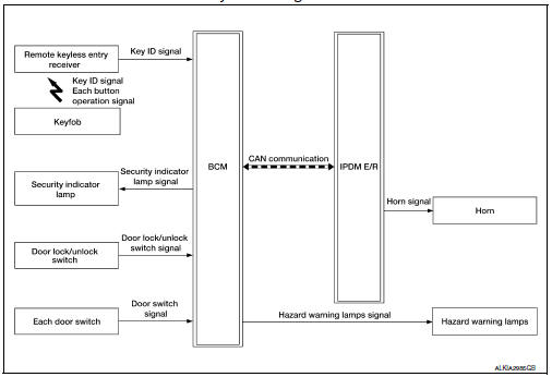
Vehicle security system : system description
- The vehicle security system has two alarm functions (theft warning alarm and panic alarm), and reduces the possibility of a theft or mischief by activating horns and headlamps intermittently.
- The panic alarm does not start when the theft warning alarm is activating, and the panic alarm stops when the theft warning alarm is activated.
The priority of the functions are as per the following.

Theft warning alarm
- The theft warning alarm function activates horns and headlamps intermittently when BCM detects that any door is opened by unauthorized means, while the system is in the ARMED state.
- Security indicator lamp on combination meter always blinks when ignition switch is in any position other than on. Security indicator lamp blinking warns that the vehicle is equipped with a vehicle security system.
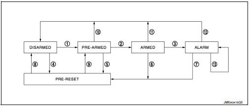
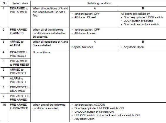
Operation flow
Note:
- Bcm ignores the door key cylinder unlock switch signal input for 1 second after the door key cylinder lock switch signal input.
- To lock/unlock all doors by operating remote controller button of Keyfob, the Keyfob must be within the detection area of remote keyless entry receiver. For details, refer to SEC-141, "NISSAN VEHICLE IMMOBILIZER SYSTEM-NATS : System Description".
Disarmed phase
The vehicle security system is not set in the disarmed phase. The vehicle security system stays in this phase while any door is open, because it is assumed that the owner is inside or nearby the vehicle. Security indicator lamp blinks every 2.4 Seconds.
When the vehicle security system is reset, each phase switches to the disarmed phase directly.
Pre-armed phase
The PRE-ARMED phase is the transient state between the DISARMED phase and the ARMED phase. This phase is maintained for 30 seconds, so that the owner can reset the setting due to a mis-operation. This phase switches to the ARMED phase when vehicle conditions are not changed for 30 seconds. Security indicator lamp illuminates while being in this phase.
To reset the PRE-ARMED phase, refer to the switching condition of No. 10 in the table above.
Armed phase
The vehicle security system is set, and bcm monitors all necessary inputs. If any door is opened without using keyfob, vehicle security system switches to the alarm phase. Security indicator lamp blinks every 2.4 Seconds.
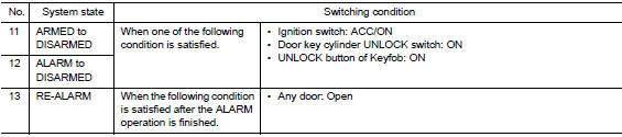
To reset the armed phase, refer to the switching condition of no. 11 In the table above.
Alarm phase
BCM transmits “Theft Warning Horn Request” signal and “High Beam Request” signal intermittently to IPDM E/R via CAN communication. In this phase, horns and headlamps are activated intermittently for approximately 50 seconds to warn that the vehicle is accessed by unauthorized means. ON/OFF timing of horns and headlamps are synchronized. After 50 seconds, the vehicle security system returns to the ARMED phase. At this time, if BCM still detects unauthorized access to the vehicle, the system is switched to the ALARM phase again. This RE-ALARM operation is carried out a maximum of 2 times.
To cancel the ALARM operation, refer to the switching condition of No. 12 in the table above.
Note:
If a battery terminal is disconnected during the alarm phase, theft warning alarm stops. But when the battery terminal is reconnected, theft warning alarm is activated again.
Pre-reset phase
The pre-reset phase is the transient state between each phase and disarmed phase.
Pre-armed phase is not available for this models.
Panic alarm
- The panic alarm function activates horns and headlamps intermittently when the owner presses the panic alarm button of keyfob outside the vehicle while the ignition switch is off.
- When bcm receives panic alarm signal from keyfob, bcm transmits “theft warning horn request” signal and “high beam request” signal intermittently to ipdm e/r via can communication. To prevent the activation due to mis-operation of keyfob by owner, the panic alarm function is activated when bcm receives the signal for 0.4 - 0.6 Seconds.
- Panic alarm operation is maintained for 25 seconds.
- Panic alarm operation is cancelled when BCM receives one of the following signals.
- LOCK button of Keyfob: ON
- Unlock button of keyfob: on
- Panic alarm button of keyfob: long pressed
 Precaution
Precaution for supplemental restraint system (srs) "air bag" and "seat
belt
pre-tensioner"
The supplemental restraint system such as “air bag” and “seat belt pre ...
 Diagnosis system (BCM)
Common item
Common item : consult function (bcm -
common item)
Application item
Consult performs the following functions via can communication with bcm.
Direct diagnostic mode
Descripti ...
Other materials:
Removal and installation
Audio unit
Exploded view
Audio unit
Audio unit bracket (LH)
Audio unit bracket (rh)
Removal and installation
Removal
Disconnect the negative battery terminal. Refer to pg-50, "removal and
installation (battery)".
Remove cluster lid c lower. Refer to ip-20, "re ...
Using the system
The NISSAN Voice Recognition system allows
hands-free operation of the Bluetooth® Phone
System.
If the vehicle is in motion, some commands may
not be available so full attention may be given to
vehicle operation.
Initialization
When the ignition switch is placed in the ON
position, NISSAN ...
Emission control information label
The emission control information label is attached
to the underside of the hood as shown.
Tire and loading information label
The cold tire pressure is shown on the Tire and
Loading Information label. The label is located as
shown.
Air conditioner specification label
The air condit ...
