Nissan Sentra Owners Manual: Forward-facing child restraint installation using LATCH
Refer to all Warnings and Cautions in the “Child safety” and “Child restraints” sections before installing a child restraint.
Follow these steps to install a forward-facing child restraint using the LATCH system:
- Position the child restraint on the seat. Always follow the child restraint manufacturer’s instructions.
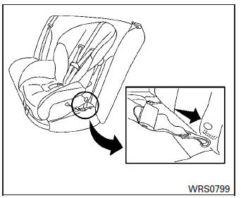
Forward-facing web-mounted – step 2
- Secure the child restraint anchor attachments
to the LATCH lower anchors. Check
to make sure the LATCH attachment is properly
attached to the lower anchors.
If the child restraint is equipped with a top tether strap, route the top tether strap and secure the tether strap to the tether anchor point. See “Installing top tether strap” in this section. Do not install child restraints that require the use of a top tether strap in seating positions that do not have a top tether anchor.
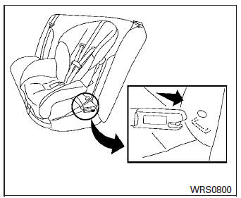
Forward-facing rigid-mounted – step 2
- The back of the child restraint should be
secured against the vehicle seatback.
If necessary, adjust or remove the head restraint/headrest to obtain the correct child restraint fit. If the head restraint/headrest is removed, store it in a secure place. Be sure to reinstall the head restraint/headrest when the child restraint is removed.
See “Head restraints/headrests” in this section for head restraint/headrest adjustment information.
If the seating position does not have an adjustable head restraint/headrest and it is interfering with the proper child restraint fit, try another seating position or a different child restraint.
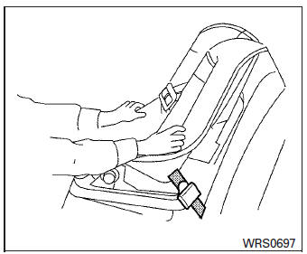
Forward-facing – step 4
- For child restraints that are equipped with
webbing-mounted attachments, remove any
additional slack from the anchor attachments.
Press downward and rearward firmly in the center of the child restraint with your knee to compress the vehicle seat cushion and seatback while tightening the webbing of the anchor attachments.
- Tighten the tether strap according to the manufacturer’s instructions to remove any slack.
Forward-facing – step 6
- After attaching the child restraint, test it before you place the child in it. Push it from side to side while holding the child restraint near the LATCH attachment path. The child restraint should not move more than 1 inch (25 mm), from side to side. Try to tug it forward and check to see if the LATCH attachment holds the restraint in place. If the restraint is not secure, tighten the LATCH attachment as necessary, or put the restraint in another seat and test it again. You may need to try a different child restraint. Not all child restraints fit in all types of vehicles.
- Check to make sure the child restraint is properly secured prior to each use. If the child restraint is loose, repeat steps 1 through 6.
 Rear-facing child restraint installation using the seat belts
WARNINGThe three-point seat belt with Automatic
Locking Retractor (ALR) must be used
when installing a child restraint. Failure to
use the ALR mode will result in the child
rest ...
 Forward-facing child restraint installation using the seat belts
WARNINGThe three-point seat belt with Automatic
Locking Retractor (ALR) must be used
when installing a child restraint. Failure to
use the ALR mode will result in the child
restrain ...
Other materials:
Air flow charts
The following charts show the button and dial
positions for MAXIMUM AND QUICK heating,
cooling or defrosting. The air recirculation
button should always be in the OFF position
for heating and defrosting.
...
P0138 HO2S2
DTC Logic
DTC DETECTION LOGIC
The heated oxygen sensor 2 has a much longer switching time between rich and
lean than the air fuel ratio (A/
F) sensor 1. The oxygen storage capacity of the three way catalyst (manifold)
causes the longer switching
time.
MALFUNCTION A
To judge the malfunction ...
Diagnosis system (BCM)
Common item
Common item : consult function (bcm - common item)
Application item
Consult performs the following functions via can communication with bcm.
System application
Bcm can perform the following functions.
Intelligent key
Intelligent key : consult function (bcm - intelligent ke ...
