Nissan Sentra Service Manual: Starter motor drive control
STARTER MOTOR DRIVE CONTROL : System Description
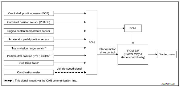
SYSTEN DIAGRAM
*1: CVT models
*2: M/T models
INPUT/OUTPUT SIGNAL CHART
| Sensor | Input signal to ECM | ECM function | Actuator | |
| Crankshaft position sensor (POS) |
|
Starter motor drive control |
|
|
| Camshaft position sensor (PHASE) | ||||
| Engine coolant temperature sensor | Engine coolant temperature | |||
| Accelerator pedal position sensor | Accelerator pedal position | |||
| Transmission range switch (CVT) | Gear position | |||
| Park/ Neutral position switch (M/T) | Gear position | |||
| Stop lamp switch | Brake pedal position | |||
| Combination meter | CAN communication | Vehicle speed signal | ||
SYSTEM DESCRIPTION
When rapid deceleration occurs during engine runs or idle speed decreases due to heavy load conditions, ECM detects a decrease in idle speed and restarts the engine to secure reliability in handleability by transmitting a cranking request signal to IPDM E/R for activating the starter motor under the following conditions:
- Selector lever: Other than P and N (CVT models)
- Shifter lever: Other than neutral position (M/T models)
- Idle switch: ON (Accelerator pedal not depressed)
- Brake switch: ON (Brake pedal depressed)
ECM transmits a control signal to IPDM E/R via BCM by CAN communication.
IPDM E/R detects an operating state of the starter motor relay and the starter motor control relay and transmits a feed back signal to ECM via CAN Communication.
 Cooling fan control
SYSTEM DIAGRAM
SYSTEM DESCRIPTION
ECM controls cooling fan speed corresponding to vehicle speed, engine coolant
temperature, refrigerant pressure,
air conditioner ON signal. Then control syst ...
 Evaporative emission system
EVAPORATIVE EMISSION SYSTEM : System Description
SYSTEM DIAGRAM
INPUT/OUTPUT SIGNAL CHART
Sensor
Input signal to ECM
ECM function
Actuator
Crankshaft position sensor (P ...
Other materials:
P1800 Intake manifold tuning valve
DTC Logic
DTC DETECTION LOGIC
DTC No.
CONSULT screen terms
(Trouble diagnosis content)
DTC detecting condition
Possible cause
P1800
VIAS S/V-1
(Variable intake air system control
solenoid valve-1)
An excessively low or high voltage signal
is sent to ECM t ...
How to use this manual
Description
This volume explains “Removal, Disassembly, Installation, Inspection and
Adjustment” and “Trouble Diagnoses”.
Terms
The captions WARNING and CAUTION warn you of steps that must be followed
to prevent personal injury
and/or damage to some part of the vehi ...
Basic inspection
Diagnosis and repair work flow
Work flow
OVERALL SEQUENCE
Detailed flow
1.Get information for symptom
Get detailed information from the customer about the symptom (the
condition and the environment when
the incident/malfunction occurs)
Check operation condition of the function tha ...
