Nissan Sentra Service Manual: Cooling fan control
SYSTEM DIAGRAM
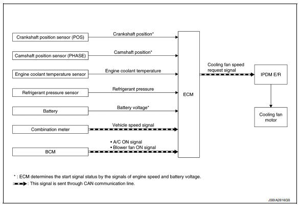
SYSTEM DESCRIPTION
ECM controls cooling fan speed corresponding to vehicle speed, engine coolant temperature, refrigerant pressure, air conditioner ON signal. Then control system has 3-step control [HIGH/LOW/OFF].
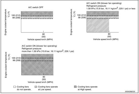
Cooling Fan Operation
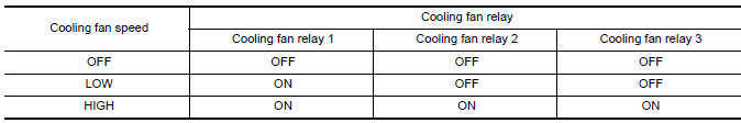
Cooling Fan Relay Operation
When IPDM E/R recieves a cooling fan speed request signal, IPDM E/R controls the cooling fan ralay 1, 2 and 3.
 Air conditioning cut control
AIR CONDITIONING CUT CONTROL : System Description
SYSTEM DIAGRAM
INPUT/OUTPUT SIGNAL CHART
Sensor
Input Signal to ECM
ECM function
Actuator
Crankshaft position sensor ( ...
 Starter motor drive control
STARTER MOTOR DRIVE CONTROL : System Description
SYSTEN DIAGRAM
*1: CVT models
*2: M/T models
INPUT/OUTPUT SIGNAL CHART
Sensor
Input signal to ECM
ECM function
Actuator
...
Other materials:
Spark plug
Exploded View
Ignition coil
Spark plug
Rocker cover
Removal and Installation
REMOVAL
Remove engine cover. Refer to EM-24, "Exploded View".
Remove ignition coil. Refer to EM-46, "Exploded View".
Remove spark plug using suitable tool.
(a) : 14 mm (0.55 in ...
Corrosion protection
Description
To provide improved corrosion prevention, the following anti-corrosive
measures have been implemented in
NISSAN production plants. When repairing or replacing body panels, it is
necessary to use the same anti-corrosive
measures.
Anti-Corrosive Wax
To improve repairability and co ...
Trip computer
When the ignition switch is placed in the ON
position, the modes of the trip
computer can be
selected by pressing the button on the
steering wheel. The following modes can be selected:
Trip A
Trip B
ECO Pedal Indicator
Instant fuel economy
Average fuel economy
Average speed
Dis ...
