Nissan Sentra Service Manual: Removal and installation
Horn
Exploded view
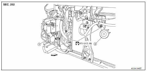
- Horn high
- Horn low
 Front
Front
Note:
Shown with the front fascia removed for clarity.
Removal and installation
Horn low
Removal
- Remove the core support cover. Refer to ext-23, "removal and installation".
- Disconnect the horn low harness connectors.
Note:
The harness connector locations prior to removal.
- Remove the horn nut and the horn low.
Installation
Installation is in the reverse order of removal.
Note:
Install the harness connector in the proper locations.
Horn high
Removal
- Partially remove the rh fender protector. Refer to ext-28, "fender protector : removal and installation - front fender protector".
- Disconnect the horn high harness connectors.
Note:
The harness connector locations prior to removal.
- Remove the horn nut and the horn high.
Installation
Installation is in the reverse order of removal.
Note:
Install the harness connector in the proper locations.
 Wiring diagram
Horn
Wiring diagram
...

Other materials:
Symptom diagnosis
Multi av system
Symptom table
Related to audio
Related to hands-free phone
Before performing diagnosis, confirm that the cellular phone being used
by the customer is compatible with
the vehicle.
It is possible that a malfunction is occurring due to a version change
of the ph ...
P0116 ECT Sensor
DTC Logic
DTC DETECTION LOGIC
DTC No.
CONSULT screen terms
(Trouble diagnosis content)
DTC detecting condition
Possible cause
P0116
ECT SEN/CIRC
(Engine coolant temperature
sensor 1 circuit range/performance)
The comparison result of signals transmitted
t ...
Roof side molding
Exploded view
Roof side molding
Roof side molding clip
Roof panel
Body side outer panel
Adhesive tape
Removal and installation
REMOVAL
ROOF SIDE MOLDING
Release roof side molding rear side clip, using a suitable tool
(A).
Clip
Front
CAUTION:
Apply protective tape ...
