Nissan Sentra Service Manual: Rear window defogger power supply and ground circuit
Description
Heats the heating wire with the power supply from the rear window defogger relay to prevent the rear window from fogging up.
Component function check
1. Check rear window defogger
Check that the heating wire of rear window defogger is heated when turning the rear window defogger switch on.
Is the inspection result normal? Yes >> rear window defogger is ok.
No >> refer to def-33, "diagnosis procedure".
Diagnosis procedure
Regarding wiring diagram information, refer to def-20, "wiring diagram".
1. Check fuses
Check if any of the following fuses in IPDM E/R are blown.
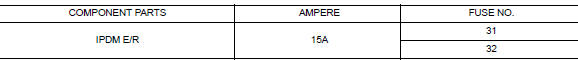
Is the inspection result normal? Yes >> go to 2.
No >> replace the blown fuse after repairing the affected circuit.
2. Check rear window defogger power supply circuit
- Turn ignition switch ON.
- Check voltage between ipdm e/r connector and ground.
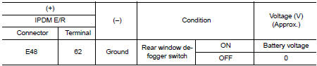
Is the inspection result normal? YES >> GO TO 3.
NO >> Perform rear window defogger relay diagnosis. Refer to DEF-32, "Diagnosis Procedure".
3. Check power supply circuit
- Turn ignition switch on.
- Check voltage between rear window defogger connector and ground.
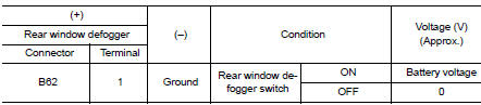
Is the inspection result normal? YES >> GO TO 4.
NO >> GO TO 5.
4. Check ground circuit
- Turn ignition switch off
- Disconnect rear window defogger.
- Check continuity between rear window defogger connector and ground.
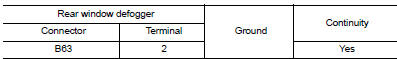
Is the inspection result normal? YES >> GO TO 6.
NO >> Repair or replace harness.
5. Check harness continuity
- Turn ignition switch OFF.
- Disconnect IPDM E/R.
- Check continuity between ipdm e/r connector and condenser connector.
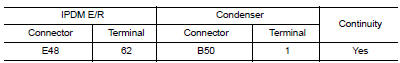
Is the inspection result normal? Yes >> replace condenser. Refer to def-49, "removal and installation".
No >> replace or repair harness.
6. Check filament
Check filament.
Refer to DEF-34, "Component Inspection".
Is the inspection result normal? YES >> Refer to GI-39, "Intermittent Incident".
NO >> Repair filament. Refer to DEF-47, "Inspection and Repair".
Component inspection
1. Check filament
Check the filament for damage or open circuits.
Refer to DEF-47, "Inspection and Repair".
Is the inspection result normal? YES >> Inspection End.
NO >> Repair filament. Refer to DEF-47, "Inspection and Repair".
 Rear window defogger relay
Description
Power is supplied to the rear window defogger with BCM control.
Component Function Check
1. Check rear window defogger relay power supply circuit
Turn ignition switch ON.
Check ...
 Driver side door mirror defogger
Description
Heats the heating wire with the power supply from the rear window defogger
relay to prevent the door mirror
from fogging up.
Component Function Check
Check that heating wire of doo ...
Other materials:
Cargo net (if so equipped)
WARNING
Properly secure all cargo with ropes or
straps to help prevent it from sliding or
shifting. In a sudden stop or collision,
unsecured cargo could cause personal
injury.
Be sure to secure all four hooks into the
retainers. The cargo restrained in the
net ...
Removal and installation
ACCELERATOR CONTROL SYSTEM
Exploded View
Accelerator pedal assembly
Brake pedal bracket
Locating hook
Locating pin
Removal and Installation
REMOVAL
Remove instrument lower panel LH. Refer to IP-21, "Removal and
Installation".
Disconnect the harness connector ...
Shift position indicator circuit
Component Parts Function Inspection
1.CHECK SHIFT POSITION INDICATOR
Start the engine.
Shift selector lever.
Check that the selector lever position and the shift position indicator
on the combination meter are identical.
Is the inspection result normal?
YES >> INSPECTION END
N ...
