Nissan Sentra Service Manual: Removal and installation
Hood
Hood assembly
Hood assembly : exploded view
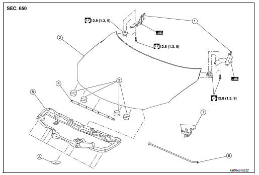
- Hood hinge (LH/RH)
- Hood assembly
- Hood bumper rubber
- Hood seal
- Hood insulator
- Hood support rod
- Hood support rod clamp
- Clip
Hood assembly : removal and installation
CAUTION:
Use two people when removing or installing hood assembly due to its heavy weight.
Use protective tape or shop cloths to protect surrounding components from damage during removal and installation of hood assembly.
REMOVAL
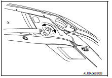
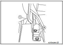
Support the hood assembly using a suitable tool.
WARNING:
Bodily injury may occur if hood assembly is not supported properly when removing hood assembly.
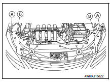
- Disconnect front washer nozzle and tube.
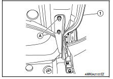
- Remove hood hinge to hood nuts (A) and then remove the hood assembly (1).
INSTALLATION
Installation is in the reverse order of removal.
Tighten hood hinge to hood nuts to specified torque. Refer to DLK-149, "HOOD ASSEMBLY : Exploded View".
CAUTION:
- Before installing the hood hinge, apply anticorrosive agent onto the surface of the vehicle.
- After installation, perform the hood assembly adjustment procedure. Refer to DLK-297, "HOOD ASSEMBLY : Adjustment".
Hood assembly : adjustment
- Hood assembly
- Front grille
- Front combination lamp
- Front fender
- Hood lock assembly
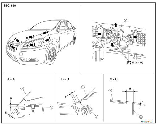
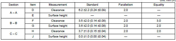
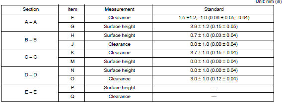
Check the clearance and the surface height between hood and each part by visual inspection and tactile feel.
If the clearance and the surface height are out of specification, adjust them according to the adjustment procedures.
CLEARANCE ADJUSTMENT
- Loosen hood hinge (LH/RH) nuts and bolts.
NOTE:
The anticorrosive agent applied between the hoodledge and the hood hinges also acts as an adhesive.
This seal must be broken before the hinges will move.
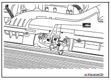
- Remove the radiator core support upper cover clips (A) and bolts (B) and remove.

- Loosen the hood lock assembly bolts.
- Adjust the hood assembly so the clearance measurements are within specifications provided. Then tighten the hood hinge nuts and bolts to specified torque. Refer to DLK-149, "HOOD ASSEMBLY : Exploded View".
- Tighten the hood lock assembly bolts to specified torque. Refer to DLK-154, "HOOD LOCK CONTROL : Exploded View".
- Install the radiator core support upper cover.
HEIGHT ADJUSTMENT
- Remove the radiator core support upper cover clips (A) and bolts (B) and remove.
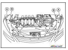
- Loosen the hood lock assembly bolts.
- Adjust the surface height of the hood assembly to front bumper fascia and front fender according to the specified values by rotating the hood bumper rubbers.
NOTE:
Only one hood bumper rubber shown for clarity.
- Temporarily tighten the hood lock assembly bolts.
- Adjust (A) and (B) as shown to the following value with hood's own weight by dropping it from approximately 200 mm (7.9 in) height or by pressing hood lightly [approximately 29 Nm (3.0 kg-m, 21 ft-lb)].
- Hood striker
- Primary latch
- Secondary striker
- Secondary latch
- 21 В± 1 mm (0.8 В± 0.04 in)
- 6.8 mm (0.27 in)
- After adjustment, tighten hood hinge nuts and bolts to the specified torque. Refer to DLK-149, "HOOD ASSEMBLY : Exploded View".
CAUTION:
- Check hood hinge rotating part for poor lubrication. If necessary, apply a suitable multi-purpose grease.
- After adjusting, apply touch-up paint (body color) to the head of hood hinge bolts and nuts.
- Tighten the hood lock assembly bolts to specified torque.
- Install the radiator core support upper cover.
- If the clearance measurements between the hood and fender cannot be corrected by adjusting the hood, the fender must be adjusted. Refer to DLK-160, "Adjustment".
Hood hinge
Hood hinge : removal and installation
REMOVAL
- Remove the fender protector. Refer to EXT-28, "FENDER PROTECTOR : Removal and Installation - Front Fender Protector".
- Remove the core support upper cover. Refer to HA-39, "Exploded View".
- Remove the front fascia. Refer to EXT-17, "Removal and Installation".
- Remove the front combination lamp. Refer to EXL-119, "Removal and Installation".
- Remove the front fender. Refer to DLK-159, "Removal and Installation".
- Remove hood hinge bolts (A) and hood hinge (1).
INSTALLATION
Installation is in the reverse order of removal.
Tighten bolts to specified torque. Refer to DLK-149, "HOOD ASSEMBLY : Exploded View".
CAUTION:
- Before installing the hood hinge, apply anticorrosive agent onto the surface of the vehicle.
- After installation, perform hood assembly adjustment procedure. Refer to DLK-297, "HOOD ASSEMBLY : Adjustment".
Hood support rod
HOOD SUPPORT ROD : Removal and Installation
REMOVAL
- Support hood assembly using a suitable tool.
WARNING:
Bodily injury may occur if hood assembly is not supported properly when removing hood support rod.
- Rotate and remove hood support rod from grommet.
- Remove grommet from hood hinge using a suitable tool, if necessary.
INSTALLATION
Installation is in the reverse order of removal.
Hood lock control
HOOD LOCK CONTROL : Exploded View
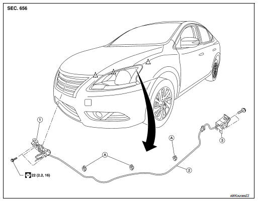
- Hood lock assembly
- Hood lock release cable
- Hood lock/fuel filler door release handle assembly
- Hood lock release cable clip
 Clip
Clip
HOOD LOCK CONTROL : Removal and Installation
REMOVAL
- Remove the fender protector (LH). Refer to EXT-28, "FENDER PROTECTOR : Removal and Installation - Front Fender Protector".
- Remove the radiator core support upper cover clips (A) and bolts (B) and remove.
- Remove the hood lock assembly bolts (A).
- Disconnect the hood lock release cable from the hood lock assembly.
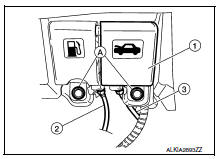
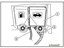
- Remove the bolts (A), then separate the hood lock/fuel filler door release handle assembly (1) from the hood lock release cable (3) and fuel filler door release cable (2).
- Remove the grommet from the dash assembly and pull the hood lock release cable into the passenger compartment.
CAUTION:
While pulling, be careful not to damage (peel) the outside of the hood lock release cable.
INSTALLATION
- Pull the hood lock release cable through the dash assembly into the engine compartment.
CAUTION:
Be careful not to bend the cable too much, keep the radius 100 mm (3.94 in) or more.
- Attach the hood lock release cable (3) and the fuel filler door release cable (2) to the hood lock/fuel filler door release handle assembly (1).
- Place hood lock/fuel filler door release handle assembly in position and retain with bolts (A).
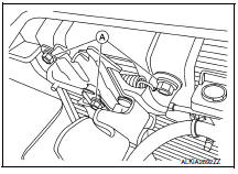
- Check that the cable is not offset from the center of the grommet and seat the grommet into the dash hole.
NOTE:
Make sure that the marked area (A) of the cable is located as shown after mounting grommet to dash upper assembly.
Apply sealant around the grommet at * mark.
- Position the hood lock release cable and clip it into place.
- Connect the hood lock release cable to the hood lock assembly.
- Perform hood fitting adjustment. Refer to DLK-297, "HOOD ASSEMBLY : Adjustment".
- Perform the hood lock control inspection.
INSPECTION
NOTE:
If the hood lock release cable is bent or deformed, replace it.
- Check that the secondary latch is properly engaged with the secondary striker and meets specification provided (B) with hood's own weight.
- Hood striker
- Primary latch
- Secondary striker
- Secondary latch
- 21 В± 1mm (0.8 В±0.04 in)
- 6.8 mm (0.27 in)
- While operating the hood lock release handle, carefully check that the front end of the hood assembly is raised and meets the specification provided (A). Also check that the hood lock release handle returns to the original position.
- Check that the hood lock release handle operating force is 49 N (5.0 kg, 11 lb) or less.
- Install so the static closing force of the hood assembly is 49 – 490 N (5.0 – 50 kg-f, 36 - 110.2 lb-f).
- Check the hood lock assembly lubrication condition. If necessary, apply a suitable multi-purpose grease as shown.
Radiator core support
Exploded View
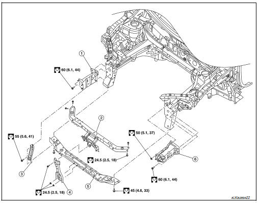
- Core support side member (RH)
- Core support upper
- Core support lower stay
- Hood lock support
- Core support lower
- Core support side member (LH)
Removal and Installation
REMOVAL
CAUTION:
Before servicing, turn ignition switch OFF, disconnect both battery terminals and wait at least three minutes.
- Disconnect the battery negative and positive terminals then wait at least three minutes. Refer to PG-50, "Removal and Installation (Battery)".
- Remove crash zone sensor. Refer to SR-25, "Removal and Installation".
- Remove radiator. Refer to CO-15, "Removal and Installation".
- Remove the condenser (if equipped). Refer to HA-39, "CONDENSER : Removal and Installation".
- Remove the horns. Refer to HRN-6, "Removal and Installation".
- Remove air guides (LH/RH).
- Remove the hood lock support bolts and hood lock support
- Remove the core support lower stay bolts and core support lower stay.
- Remove the core support lower bolts and core support lower.
- Remove the core support side member nuts and bolts and remove the core support side member, if necessary.
INSTALLATION
Installation is in the reverse order of removal.
Tighten bolts to specification. Refer to DLK-157, "Exploded View".
CAUTION:
After installation, perform hood fitting adjustment. Refer to DLK-150, "HOOD ASSEMBLY : Adjustment".
Front fender
Exploded View
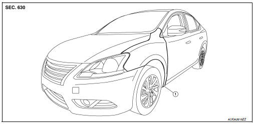
- Front fender
Removal and Installation
REMOVAL
- Remove the front combination lamp. Ref to EXL-119, "Removal and Installation".
- Remove the front bumper fascia. Refer to EXT-17, "Removal and Installation".
- Remove the front fender protector. Refer to EXT-28, "FENDER PROTECTOR : Removal and Installation - Front Fender Protector".
- Remove the front fender bolts and the front fender.
CAUTION:
Use shop cloths to protect the body from being damaged during removal and installation.
INSTALLATION
Installation is in the reverse order of removal.
CAUTION:
After installation, perform fender adjustment procedure. Refer to DLK-307, "Adjustment".
Adjustment
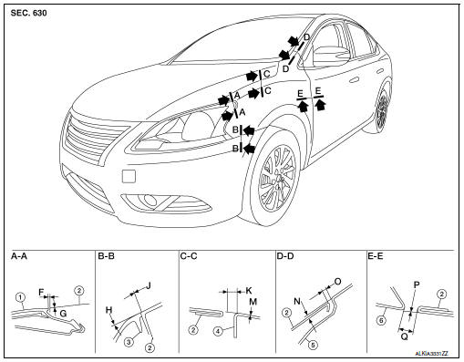
- Front combination lamp assembly
- Fender
- Front bumper fascia
- Hood assembly
- Body side outer
- Front door
Check the clearance and the surface height between hood and each part by visual inspection and tactile feel.
If the clearance and the surface height are out of specification, adjust them according to the adjustment procedures.
Adjustment
- Remove front bumper fascia. Refer to EXT-17, "Removal and Installation".
- Remove the front fender protector. Refer to EXT-28, "FENDER PROTECTOR : Removal and Installation - Front Fender Protector".
- Loosen the front fender bolts.
- Adjust the clearance (Q) and surface height (P) between the front fender and the front door.
- Tighten the rear upper and lower front fender bolts.
- Adjust the clearance (K) and surface height (M) between the front fender and the hood.
- Adjust the clearance (O) and surface height (N) between the front fender and the body side outer.
- Tighten the inner front fender bolts.
- Adjust the clearance (J) and the surface height (H) between the front fender and the front fascia.
- Tighten the front fender to front fascia and bracket screws.
- Install front bumper fascia. Refer to EXT-17, "Removal and Installation".
- Install front combination lamp.Refer to EXL-119, "Removal and Installation"
- Install the front fender protector. Refer to EXT-28, "FENDER PROTECTOR : Removal and Installation - Front Fender Protector".
CAUTION:
- If the clearance measurements cannot be corrected by adjusting the fender, adjust the following as necessary.
- Hood assembly: Refer to DLK-150, "HOOD ASSEMBLY : Adjustment".
- Front door: Refer to DLK-164, "DOOR ASSEMBLY : Adjustment".
- After adjusting, apply touch-up paint (body color) to the head of the front fender bolts.
 Symptom diagnosis
Power door lock system symptoms
Symptom table
Door lock/unlock function malfunction
Note:
Before performing the diagnosis in the following table, check –≤–Ç—öWORK
FLOW–≤–Ç—ú. Refer to DLK-24 ...
 Front door
Door assembly
Door assembly : removal and installation
CAUTION:
Use two people when removing or installing the front door assembly
due to its heavy weight.
When removing and installing fro ...
Other materials:
Precaution for Supplemental Restraint System (SRS) "AIR BAG" and "SEAT BELT
PRE-TENSIONER"
The Supplemental Restraint System such as –≤–Ç—öAIR BAG–≤–Ç—ú and –≤–Ç—öSEAT BELT PRE-TENSIONER–≤–Ç—ú,
used along
with a front seat belt, helps to reduce the risk or severity of injury to the
driver and front passenger for certain
types of collision. Information necessary to service the system ...
Heater and air conditioner (automatic) (if so equipped)
Temperature control buttons (driver’s
side)
(front defroster) button
(rear window defroster)
button
Display screen
MODE (manual air flow control) button
Fresh air intake button
Air recirculation button
Temperature control buttons (passenger’s
side)
DUAL button
...
Door lock
Front door lock
Front door lock : exploded view
Outside handle bracket
Front gasket
Outside handle
Door lock assembly
Door striker
Door key cylinder rod
Inside handle assembly
Outside handle escutcheon
Rear gasket
Front door lock : removal and installation
CAUTION:
Befor ...
