Nissan Sentra Service Manual: Power supply and ground circuit
Diagnosis procedure
Regarding wiring diagram information, refer to bcs-51, "wiring diagram".
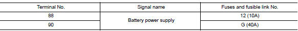
1.Check fuses and fusible link
Check that the following fuses and fusible link are not blown.
Is the fuse blown? YES >> Replace the blown fuse or fusible link after repairing the affected circuit.
NO >> GO TO 2.
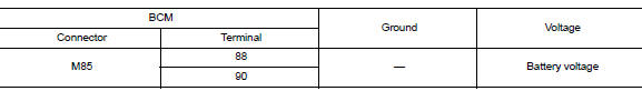
2.Check power supply circuit
- Disconnect bcm connector m85.
- Check voltage between bcm connector m85 and ground.
Is the inspection result normal? YES >> GO TO 3.
NO >> Repair harness or connector.
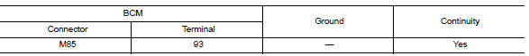
3.Check ground circuit
Check continuity between bcm connector m85 and ground.
Is the inspection result normal? YES >> Inspection End.
NO >> Repair harness or connector.
Combination meter buzzer
Component function check
1.Check function
- Select intelligent key of bcm using consult.
- Select inside buzzer in active test mode.
- Touch Key, Knob or Take Out to check that it works normally.
Is the inspection result normal? Yes >> Combination meter buzzer is OK.
No >> Refer to DLK-91, "Diagnosis Procedure".
Diagnosis Procedure
1.CHECK METER BUZZER CIRCUIT
Refer to WCS-28, "Component Function Check".
Is the inspection result normal? Yes >> GO TO 2.
No >> Repair or replace harness.
2.CHECK INTERMITTENT INCIDENT
Refer to GI-39, "Intermittent Incident".
>> Inspection End.
 DTC/circuit diagnosis
U1000 CAN COMM CIRCUIT
Description
Refer to lan-7, "can communication system : system description".
Dtc logic
Dtc detection logic
Note:
U1000 can be set if a module harness was disconn ...
 Door lock actuator
Driver side
Driver side : component function check
1.CHECK FUNCTION
Select DOOR LOCK of BCM using CONSULT.
Select DOOR LOCK in ACTIVE TEST mode.
Touch ALL LOCK or ALL UNLK to check that it w ...
Other materials:
Basic inspection
Diagnosis and repair work flow
Work Flow
Overall sequence
Detailed flow
1. Get information for symptom
Get the detailed information from the customer about the symptom (the
condition and the environment when
the incident/malfunction occurred).
>> Go to 2.
2. Check dtc
Check ...
DTC/circuit diagnosis
U1000 CAN COMM CIRCUIT
Description
CAN (Controller Area Network) is a serial communication system for real time
application. It is an on-vehicle
multiplex communication system with high data communication speed and excellent
error detection ability.
Many electronic control units are equip ...
P0711 Transmission fluid temperature sensor A
DTC Logic
DTC DETECTION LOGIC
DTC
CONSULT screen terms
(Trouble diagnosis content)
DTC detection condition
Possible causes
P0711
FLUID TEMP SENSOR A
(Transmission Fluid Temperature
Sensor A Circuit Range/
Performance)
When any of 1 or 2 is satisfied:
...
