Nissan Sentra Service Manual: DTC/circuit diagnosis
U1000 CAN COMM CIRCUIT
Description
CAN (Controller Area Network) is a serial communication system for real time application. It is an on-vehicle multiplex communication system with high data communication speed and excellent error detection ability.
Many electronic control units are equipped onto vehicles, and each control unit shares information and links with other control units during operation (not independent). In CAN communication, control units are connected with two communication lines (CAN-H line, CAN-L line) allowing a high rate of information transmission with less wiring. Each control unit transmits/receives data but selectively reads required data only. Refer to LAN-30, "CAN COMMUNICATION SYSTEM : CAN Communication Signal Chart".
DTC Logic
DTC DETECTION LOGIC
| DTC | Items (CONSULT screen terms) | DTC detection condition | Possible cause |
| U1000 | CAN COMM CIRCUIT | When A/C auto amp. is not transmitting or receiving CAN communication signal for 2 or more seconds. | CAN communication system |
DTC CONFIRMATION PROCEDURE
1.PERFORM SELF-DIAGNOSIS
 With CONSULT
- Turn ignition switch ON and wait for 2 seconds or more.
- Using CONSULT, perform “SELF-DIAGNOSIS RESULTS” of HVAC.
- Check if any DTC No. is displayed in the self-diagnosis results.
Is DTC detected? YES >> Refer to HAC-58, "Diagnosis Procedure".
NO >> Refer to GI-39, "Intermittent Incident".
Diagnosis Procedure
1.CHECK CAN COMMUNICATION SYSTEM
Check CAN communication system. Refer to LAN-16, "Trouble Diagnosis Flow Chart".
>> Inspection End.
U1010 CONTROL UNIT (CAN)
Description
Initial diagnosis of A/C auto amp.
DTC Logic
DTC DETECTION LOGIC
| DTC | Items (CONSULT screen terms) | DTC detection condition | Possible cause |
| U1010 | CONTROL UNIT (CAN) | When detecting error during the initial diagnosis of CAN controller of A/C auto amp. | A/C auto amp. |
DTC CONFIRMATION PROCEDURE
1.PERFORM SELF-DIAGNOSIS
 With CONSULT
- Turn ignition switch ON.
- Using CONSULT, perform “SELF-DIAGNOSIS RESULTS” of HVAC.
- Check if any DTC No. is displayed in the self-diagnosis results.
Is DTC detected? YES >> Refer to HAC-59, "Diagnosis Procedure".
NO >> Inspection End.
Diagnosis Procedure
1.REPLACE A/C AUTO AMP.
Replace A/C auto amp. Refer to HAC-105, "Removal and Installation".
>> Inspection End.
B2578, B2579 IN-VEHICLE SENSOR
DTC Logic
DTC DETECTION LOGIC
NOTE:
- If DTC is displayed along with DTC U1000, first perform the trouble diagnosis for DTC U1000. Refer to HAC- 58, "DTC Logic".
- If DTC is displayed along with DTC U1010, first perform the trouble diagnosis for DTC U1010. Refer to HAC- 59, "DTC Logic".
| DTC | Items (CONSULT screen terms) | DTC detection condition | Possible cause |
| B2578 | IN-VEHICLE SENSOR | The in-vehicle sensor recognition temperature is too high. |
|
| B2579 | The in-vehicle sensor recognition temperature is too low. |
DTC CONFIRMATION PROCEDURE
1.PERFORM DTC CONFIRMATION PROCEDURE
 With CONSULT
- Turn ignition switch ON.
- Using CONSULT, perform “SELF-DIAGNOSIS RESULTS” of HVAC.
- Check if any DTC No. is displayed in the self-diagnosis results.
Is DTC detected? YES >> Refer to HAC-60, "Diagnosis Procedure".
NO >> Inspection End.
Diagnosis Procedure
Regarding Wiring Diagram information, refer to HAC-41, "Wiring Diagram".
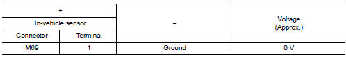
1.Check in-vehicle sensor power supply
- Turn ignition switch OFF.
- Disconnect in-vehicle sensor connector.
- Turn ignition switch ON.
- Check voltage between in-vehicle sensor harness connector and ground.
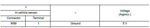
Is the inspection result normal? Yes >> go to 2.
No >> go to 4.
2.Check in-vehicle sensor ground circuit
- Turn ignition switch OFF.
- Check continuity between front in-vehicle sensor harness connector and ground.
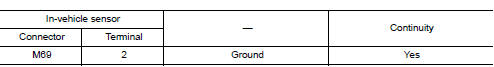
Is the inspection result normal? YES >> GO TO 3.
NO >> Repair harness or connector.
3.CHECK IN-VEHICLE SENSOR
Check in-vehicle sensor. Refer to HAC-61, "Component Inspection".
Is the inspection result normal? YES >> Replace A/C auto amp. Refer to HAC-105, "Removal and Installation".
NO >> Replace in-vehicle sensor. Refer to HAC-107, "Removal and Installation".
4.Check in-vehcile sensor power supply circuit for open
- Turn ignition switch OFF.
- Disconnect A/C auto amp. connector.
- Check continuity between in-vehicle sensor harness connector and A/C auto amp. harness connector.
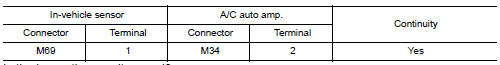
Is the inspection result normal? Yes >> go to 5.
No >> repair harness or connector.
5.Check in-vehicle sensor power supply circuit for ground short
Check continuity between in-vehicle sensor harness connector and ground.
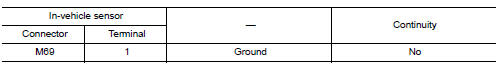
Is the inspection result normal? Yes >> go to 6.
No >> repair harness or connector.
6.Check in-vehicle sensor power supply circuit for power short
- Turn ignition switch ON.
- Check voltage between in-vehicle sensor harness connector and ground.
Is the inspection result normal? YES >> Replace A/C auto amp. Refer to HAC-105, "Removal and Installation".
NO >> Repair harness or connector.
Component Inspection
1.Check in-vehicle sensor
- Turn ignition switch OFF.
- Disconnect in-vehicle sensor connector.
- Check resistance between in-vehicle sensor terminals.
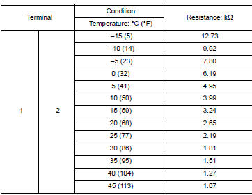
Is the inspection result normal? YES >> Inspection End.
NO >> Replace in-vehicle sensor. Refer to HAC-107, "Removal and Installation".
B257B, B257C AMBIENT SENSOR
DTC Logic
DTC DETECTION LOGIC
NOTE:
- If DTC is displayed along with DTC U1000, first perform the trouble diagnosis for DTC U1000. Refer to HAC- 58, "DTC Logic".
- If DTC is displayed along with DTC U1010, first perform the trouble diagnosis for DTC U1010. Refer to HAC- 59, "DTC Logic".
| DTC | Items (CONSULT screen terms) | DTC detection condition | Possible cause |
| B257B | AMBIENT SENSOR | The ambient sensor recognition temperature is too high. |
|
| B257C | The ambient sensor recognition temperature is too low. |
DTC CONFIRMATION PROCEDURE
1.PERFORM DTC CONFIRMATION PROCEDURE
 With CONSULT
- Turn ignition switch ON.
- Using CONSULT, perform “SELF-DIAGNOSIS RESULTS” of HVAC.
- Check if any DTC No. is displayed in the self-diagnosis results
Is DTC detected? YES >> Refer to HAC-63, "Diagnosis Procedure".
NO >> Inspection End.
Diagnosis Procedure
Regarding Wiring Diagram information, refer to HAC-41, "Wiring Diagram".
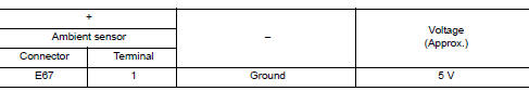
1.Check ambient sensor power supply
- Turn ignition switch OFF.
- Disconnect ambient sensor connector.
- Turn ignition switch ON.
- Check voltage between ambient sensor harness connector and ground.
Is the inspection result normal? Yes >> go to 2.
No >> go to 4.
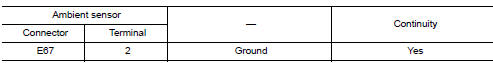
2.Check ambient sensor ground circuit
- Turn ignition switch off.
- Check continuity between ambient sensor harness connector and ground.
Is the inspection result normal? Yes >> go to 3.
No >> repair harness or connector
3.Check ambient sensor
Check ambient sensor. Refer to hac-64, "component inspection".
Is the inspection result normal? Yes >> replace a/c auto amp. Refer to hac-105, "removal and installation".
No >> replace ambient sensor. Refer to hac-106, "removal and installation".
4.Check ambient sensor power supply circuit for open
- Turn ignition switch off.
- Disconnect a/c auto amp.Connector.
- Check continuity between ambient sensor harness connector and a/c auto amp. Harness connector.
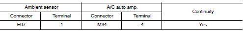
Is the inspection result normal? Yes >> go to 5.
No >> repair harness or connector.
5.Check ambient sensor power supply circuit for ground short
Check continuity between ambient sensor harness connector and ground.
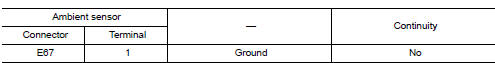
Is the inspection result normal? Yes >> go to 6.
No >> repair harness or connector.
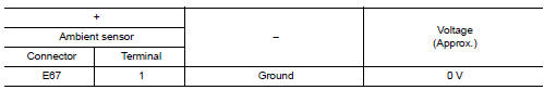
6.Check ambient sensor power supply circuit for power short
- Turn ignition switch on.
- Check voltage between ambient sensor harness connector and ground.
Is the inspection result normal? Yes >> replace a/c auto amp. Refer to hac-105, "removal and installation".
No >> repair harness or connector.
Component Inspection
1.Check ambient sensor
- Turn ignition switch off.
- Disconnect ambient sensor connector.
- Check resistance between ambient sensor terminals.
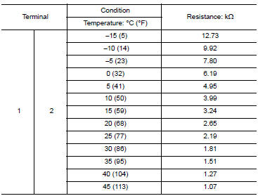
Is the inspection result normal? Yes >> inspection end.
No >> replace ambient sensor. Refer to hac-106, "removal and installation".
B2581, B2582 INTAKE SENSOR
DTC Logic
Dtc detection logic
NOTE:
- If DTC is displayed along with DTC U1000, first perform the trouble diagnosis for DTC U1000. Refer to HAC- 58, "DTC Logic".
- If DTC is displayed along with DTC U1010, first perform the trouble diagnosis for DTC U1010. Refer to HAC- 59, "DTC Logic".
| DTC | Items (CONSULT screen terms) | DTC detection condition | Possible cause |
| B2581 | INTAKE SENSOR | The intake sensor recognition temperature is too high. |
|
| B2582 | The intake sensor recognition temperature is too low. |
DTC CONFIRMATION PROCEDURE
1.PERFORM DTC CONFIRMATION PROCEDURE
 With CONSULT
- Turn ignition switch ON.
- Using CONSULT, perform “SELF-DIAGNOSIS RESULTS” of HVAC.
- Check if any DTC No. is displayed in the self-diagnosis results.
Is DTC detected? YES >> Refer to HAC-66, "Diagnosis Procedure".
NO >> Inspection End.
Diagnosis Procedure
Regarding Wiring Diagram information, refer to HAC-41, "Wiring Diagram".
1.Check intake sensor power supply
- Turn ignition switch OFF.
- Disconnect intake sensor connector.
- Turn ignition switch ON.
- Check voltage between intake sensor harness connector and ground.
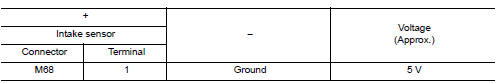
Is the inspection result normal? YES >> GO TO 2.
NO >> GO TO 4.
2.Check intake sensor ground circuit
- Turn ignition switch OFF.
- Check continuity between intake sensor harness connector and ground.
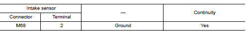
Is the inspection result normal? Yes >> go to 3.
No >> repair harness or connector.
3.Check intake sensor
Check intake sensor. Refer to hac-67, "component inspection".
Is the inspection result normal? Yes >> replace a/c auto amp. Refer to hac-105, "removal and installation".
No >> replace intake sensor. Refer to hac-109, "removal and installation".
4.Check intake sensor power supply circuit for open
- Turn ignition switch off.
- Disconnect a/c auto amp. Connector.
- Check continuity between intake sensor harness connector and a/c auto amp. Harness connector.
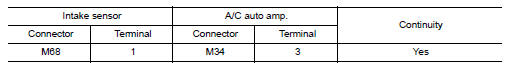
Is the inspection result normal? Yes >> go to 5.
No >> repair harness or connector.
5.Check intake sensor power supply circuit for short to ground
Check continuity between intake sensor harness connector and ground.
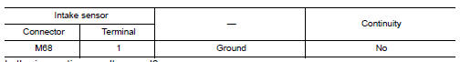
Is the inspection result normal? Yes >> go to 6.
No >> repair harness or connector.
6.Check intake sensor power supply circuit for short to voltage
- Turn ignition switch on.
- Check voltage between intake sensor harness connector and ground.
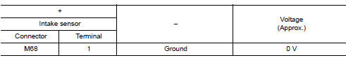
Is the inspection result normal? Yes >> replace a/c auto amp. Refer to hac-105, "removal and installation".
No >> repair harness or connector.
Component Inspection
1.Check intake sensor
- Turn ignition switch off.
- Disconnect intake sensor connector
- Check resistance between intake sensor terminals.
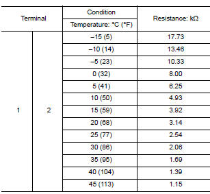
Is the inspection result normal? YES >> Inspection End.
NO >> Replace intake sensor. Refer to HAC-109, "Removal and Installation".
B2630, B2631 SUNLOAD SENSOR
DTC Logic
Dtc detection logic
Note:
- Sunload sensor may register a malfunction when indoors, at dusk, or
at other times when light is insufficient.
When performing the diagnosis indoors, light the sunload sensor with a lamp (60w or more).
- If DTC is displayed along with DTC U1000 or U1010, first diagnose the DTC U1000 or U1010. Refer to HAC- 58, "DTC Logic" (U1000) or HAC-59, "DTC Logic" (U1010).
| Dtc | Items (consult screen terms) | Diagnostic item is detected when... | Possible cause |
| B2630 | Sunload sen (short) | Detected calorie at sunload sensor 1677 w/m2 (1442 kcal/m2В·h) or more |
|
| B2631 | Sunload sen (open) | Detected calorie at sunload sensor 33 w/m2 (28 kcal/m2В·h) |
Dtc confirmation procedure
1.Check with self-diagnosis function of consult
- Using consult, perform “self-diagnosis results” of hvac.
- Check if any dtc no. Is displayed in the self-diagnosis results.
NOTE:
- If dtc is displayed along with dtc u1000 or u1010, first diagnose the dtc u1000 or u1010. Refer to hac- 58, "dtc logic" (u1000) or hac-59, "dtc logic" (u1010).
- Sunload sensor may register a malfunction when indoors, at dusk, or
at other times when light is insufficient.
When performing the diagnosis indoors, light the sunload sensor with a lamp (60W or more).
Is dtc no.“B2630” or “b2631” displayed? Yes >> perform trouble diagnosis for the sunload sensor. Refer to hac-69, "diagnosis procedure".
No >> inspection end.
Diagnosis Procedure
Regarding Wiring Diagram information, refer to HAC-41, "Wiring Diagram".
1.Check sunload sensor power supply
- Disconnect sunload sensor connector.
- Turn ignition switch on.
- Check voltage between sunload sensor harness connector and ground.
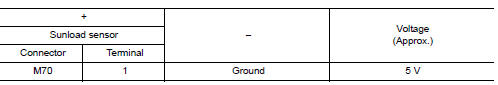
Is the inspection result normal? YES >> GO TO 2.
NO >> GO TO 4.
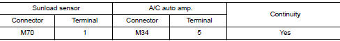
2.Check continuity between sunload sensor and a/c auto amp.
- Turn ignition switch OFF.
- Disconnect A/C auto amp. connector.
- Check continuity between sunload sensor harness connector and a/c auto amp. Harness connector.
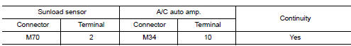
Is the inspection result normal? YES >> GO TO 3.
NO >> Repair harness or connector.
3.Check sunload sensor
- Reconnect sunload sensor connector and a/c auto amp. Connector.
- Check sunload sensor. Refer to hac-70, "component inspection".
Is the inspection result normal? YES >> Replace A/C auto amp. Refer to HAC-105, "Removal and Installation".
NO >> Replace sunload sensor. Refer to HAC-108, "Removal and Installation".
4.Check continuity between sunload sensor and a/c auto amp.
- Turn ignition switch off.
- Disconnect a/c auto amp. Connector.
- Check continuity between sunload sensor harness connector and A/C auto amp. harness connector.
- Check continuity between sunload sensor harness connector and ground.
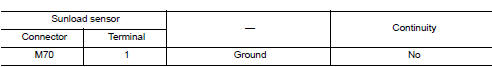
Is the inspection result normal? Yes >> replace a/c auto amp. Refer to hac-105, "removal and installation".
No >> repair harness or connector.
Component Inspection
1.Check sunload sensor
- Turn ignition switch on.
- Check voltage between A/C auto amp. harness connector and ground.
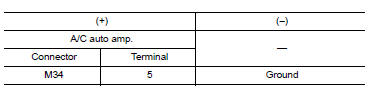
Note:
Select a place in direct sunlight when checking sunload sensor.
Is the inspection result normal? Yes >> inspection end.
No >> replace sunload sensor. Refer to hac-108, "removal and installation".
B27A2, B27A3, B27A4, B27A5 AIR MIX DOOR MOTOR (DRIVER SIDE)
DTC Logic
Dtc detection logic
Note:
- If DTC is displayed along with DTC U1000, first perform the trouble diagnosis for DTC U1000. Refer to HAC- 58, "DTC Logic".
- If DTC is displayed along with DTC U1010, first perform the trouble diagnosis for DTC U1010. Refer to HAC- 59, "DTC Logic".
- If air mix door motors dtc (b27a2 – b27a5) are detected, there is probably a disconnected connector or an open circuit in air mix door motor drive power supply harness.
| Dtc | Items (consult screen terms) | Dtc detection condition | Possible cause |
| B27a2 | DR AIR MIX DOOR MOT | Short or open circuit of air mix door motor drive signal terminal 1. |
|
| B27a3 | Short or open circuit of air mix door motor drive signal terminal 2. | ||
| B27a4 | Short or open circuit of air mix door motor drive signal terminal 3. | ||
| B27a5 | v |
Dtc confirmation procedure
1.Perform dtc confirmation procedure
 With consult
- Turn ignition switch on.
- Select “self diagnostic result” mode of “hvac” using consult.
- Check dtc.
Is DTC detected? YES >> Refer to HAC-74, "Diagnosis Procedure".
NO >> Inspection End.
Diagnosis Procedure
Regarding Wiring Diagram information, refer to HAC-41, "Wiring Diagram".
1.Check air mix door motor power supply
- Turn ignition switch off
- Disconnect air mix door motor connector.
- Turn ignition switch ON.
- Check voltage between air mix door motor harness connector and ground.
Is the inspection result normal? Yes >> go to 2.
No >> repair harness or connector between air mix door motor and fuse.
2.Check air mix door motor lh drive signal circuit for open
- Turn ignition switch off.
- Disconnect a/c auto amp. Connector.
- Check continuity between air mix door motor lh harness connector and a/c auto amp. Harness connector.
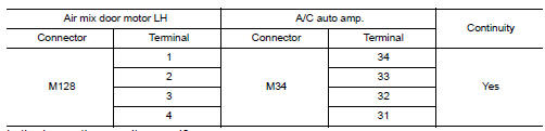
Is the inspection result normal? Yes >> go to 3.
No >> repair harness or connector.
3.Check air mix door motor lh drive signal circuit for short
Check continuity between air mix door motor LH harness connector and A/C auto amp. harness connector.
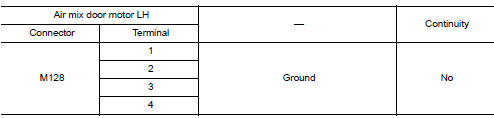
Is the inspection result normal? Yes >> go to 4.
No >> repair harness or connector.
4.Check air mix door motor lh
Check air mix door motor lh. Refer to hac-75, "component inspection".
Is the inspection result normal? Yes >> replace a/c auto amp. Refer to hac-105, "removal and installation".
No >> replace air mix door motor lh. Refer to hac-112, "air mix door motor : removal and installation - air mix door motor lh".
Component Inspection
1.Check air mix door motor lh
- Remove air mix door motor lh. Refer to hac-112, "air mix door motor : removal and installation - air mix door motor lh".
- Check resistance between air mix door motor LH terminals. Refer to applicable table for the normal value.
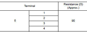
Is the inspection result normal? YES >> Inspection End.
NO >> Replace air mix door motor LH. Refer to HAC-112, "AIR MIX DOOR MOTOR : Removal and Installation - Air Mix Door Motor LH".
B27AA, B27AB, B27AC, B27AD AIR MIX DOOR MOTOR (PASSENGER SIDE)
DTC Logic
Dtc detection logic
Note:
- If dtc is displayed along with dtc u1000, first perform the trouble diagnosis for dtc u1000. Refer to hac- 58, "dtc logic"
- If dtc is displayed along with dtc u1010, first perform the trouble diagnosis for dtc u1010. Refer to hac- 59, "dtc logic"
- If air mix door motors dtc (b27a2 – b27a5) are detected, there is probably a disconnected connector or an open circuit in air mix door motor drive power supply harness.
| Dtc | Items (consult screen terms) | Dtc detection condition | Possible cause |
| B27aa | As air mix door mot | Short or open circuit of air mix door motor drive signal terminal 1. |
|
| B27AB | Short or open circuit of air mix door motor drive signal terminal 2. | ||
| B27ac | Short or open circuit of air mix door motor drive signal terminal 3. | ||
| B27ad | Short or open circuit of air mix door motor drive signal terminal 4. |
Dtc confirmation procedure
1.Perform dtc confirmation procedure
 With consult
- Turn ignition switch on.
- Select “self diagnostic result” mode of “hvac” using consult.
- Check dtc.
Is DTC detected? YES >> Refer to HAC-74, "Diagnosis Procedure".
NO >> Inspection End.
Diagnosis Procedure
Regarding wiring diagram information, refer to hac-41, "wiring diagram".
1.Check air mix door motor rh power supply
- Turn ignition switch off.
- Disconnect air mix door motor RH connector.
- Turn ignition switch ON.
- Check voltage between air mix door motor rh harness connector and ground.
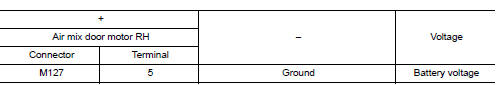
Is the inspection result normal? Yes >> go to 2.
No >> repair harness or connector.
2.Check air mix door motor drive signal circuit for open
- Turn ignition switch off.
- Disconnect a/c auto amp. Connector.
- Check continuity between air mix door motor rh harness connector and a/c auto amp. Harness connector.
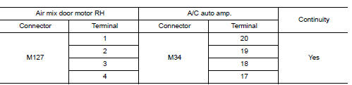
Is the inspection result normal? Yes >> go to 3.
No >> repair harness or connector.
3.Check air mix door motor RH drive signal circuit for short
Check continuity between air mix door motor rh harness connector and a/c auto amp. Harness connector.
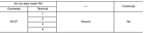
Is the inspection result normal? Yes >> go to 4.
No >> repair harness or connector.
4.Check air mix door motor rh
Check air mix door motor rh. Refer to hac-75, "component inspection".
Is the inspection result normal? Yes >> replace a/c auto amp. Refer to hac-105, "removal and installation".
No >> replace air mix door motor rh. Refer to hac-112, "air mix door motor : removal and installation - air mix door motor rh".
Component Inspection
1.Check air mix door motor RH
- Remove air mix door motor rh. Refer to hac-112, "air mix door motor : removal and installation -air mix door motor rh".
- Check resistance between air mix door motor rh terminals. Refer to applicable table for the normal value.
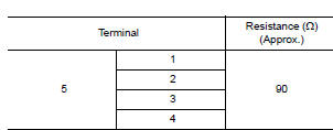
Is the inspection result normal? Yes >> inspection end.
NO >> Replace air mix door motor RH. Refer to HAC-112, "AIR MIX DOOR MOTOR : Removal and Installation - Air Mix Door Motor RH".
B27A6, B27A7, B27A8, B27A9 MODE DOOR MOTOR
DTC Logic
Dtc detection logic
Note:
- If dtc is displayed along with dtc u1000, first perform the trouble diagnosis for dtc u1000. Refer to hac- 58, "dtc logic".
- If dtc is displayed along with dtc u1010, first perform the trouble diagnosis for dtc u1010. Refer to hac- 59, "dtc logic".
- If mode door motors dtc (b27a6 – b27a9) are detected, there is probably a disconnected connector or an open circuit in mode door motor drive power supply harness.
| Dtc | Items (consult screen terms) | Dtc detection condition | Possible cause |
| B27A6 | MODE DOOR MOTOR | Short or open circuit of mode door motor drive signal terminal 1. |
|
| B27A7 | Short or open circuit of mode door motor drive signal terminal 2. | ||
| B27A8 | Short or open circuit of mode door motor drive signal terminal 3. | ||
| B27A9 | Short or open circuit of mode door motor drive signal terminal 4. |
DTC CONFIRMATION PROCEDURE
1.PERFORM DTC CONFIRMATION PROCEDURE
 With CONSULT
- Turn ignition switch ON.
- Select “Self Diagnostic Result” mode of “HVAC” using CONSULT.
- Check DTC.
Is DTC detected? YES >> Refer to HAC-77, "Diagnosis Procedure".
NO >> Inspection End.
Diagnosis Procedure
Regarding Wiring Diagram information, refer to HAC-41, "Wiring Diagram".
1.Check mode door motor power supply
- Turn ignition switch OFF.
- Disconnect mode door motor connector.
- Turn ignition switch ON.
- Check voltage between mode door motor harness connector and ground.
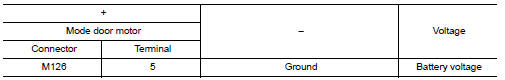
Is the inspection result normal? Yes >> go to 2.
No >> repair harness or connector between mode door motor and fuse.
2.Check mode door motor drive signal circuit for open
- Turn ignition switch off.
- Disconnect a/c auto amp. Connector.
- Check continuity between mode door motor harness connector and a/c auto amp. Harness connector.
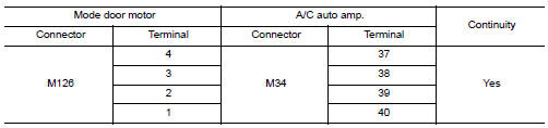
Is the inspection result normal? Yes >> go to 3.
No >> repair harness or connector.
3.Check mode door motor drive signal circuit for short
Check continuity between mode door motor harness connector and a/c auto amp. Harness connector.
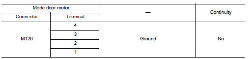
Is the inspection result normal? YES >> GO TO 4.
NO >> Repair harness or connector.
4.Check mode door motor
Check mode door motor. Refer to HAC-78, "Component Inspection".
Is the inspection result normal? YES >> Replace A/C auto amp. Refer to HAC-105, "Removal and Installation".
NO >> Replace mode door motor. Refer to HAC-112, "MODE DOOR MOTOR : Removal and Installation".
Component Inspection
1.Check mode door motor
- Remove mode door motor. Refer to hac-112, "mode door motor : removal and installation".
- Check resistance between mode door motor terminals. Refer to applicable table for the normal value.
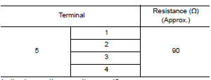
Is the inspection result normal? Yes >> inspection end.
No >> replace mode door motor. Refer to hac-112, "mode door motor : removal and installation".
B27A0, B27A1 INTAKE DOOR MOTOR
DTC Logic
Dtc detection logic
Note:
- If dtc is displayed along with dtc u1000, first perform the trouble diagnosis for dtc u1000. Refer to hac- 58, "dtc logic".
- If DTC is displayed along with DTC U1010, first perform the trouble diagnosis for DTC U1010. Refer to HAC- 59, "DTC Logic".
| Dtc | Items (consult screen terms) | Dtc detection condition* | Possible cause |
| B27A0 | Intake door motor | Pbr opening angle of intake door motor is 50% or more. (Pbr feedback signal voltage of intake door motor is 2.5 V or more) |
|
| B27A1 | Pbr opening angle of intake door motor is 30% or less. (Pbr feedback signal voltage of intake door motor is 1.5 V or less) |
*: A/c auto amp. Operates intake door motor according to target value of pbr opening angle at 40% when performing self-diagnosis.
Dtc confirmation procedure
1.Perform dtc confirmation procedure
 With consult
- Start engine.
- Select “Self Diagnostic Result” mode of “HVAC” using CONSULT.
- Check dtc.
Is DTC detected? YES >> Refer to HAC-79, "Diagnosis Procedure".
NO >> Inspection End.
Diagnosis Procedure
Regarding wiring diagram information, refer to hac-41, "wiring diagram".
1.Check intake door motor operation
- Turn ignition switch on.
- Operate intake switch and check by operation sound that intake door motor operates
Does the intake door motor operate? Yes >> go to 2.
No >> go to 8.
2.Check intake door motor PBR power supply
- Disconnect intake door motor connector.
- Turn ignition switch on.
- Check voltage between intake door motor harness connector and ground.
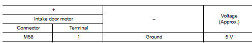
Is the inspection result normal?
Yes >> go to 3.
No >> go to 7.
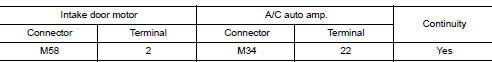
3.Check intake door motor pbr ground circuit for open
- Turn ignition switch off.
- Disconnect a/c auto amp. Connector.
- Check continuity between intake door motor harness connector and A/C auto amp. harness connector.
Is the inspection result normal? Yes >> go to 4.
No >> repair harness or connector.
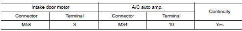
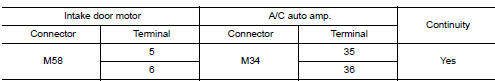
4.Check intake door motor PBR feedback signal circuit for open
Check continuity between intake door motor harness connector and a/c auto amp. Harness connector.
Is the inspection result normal? Yes >> go to 5.
No >> repair harness or connector.
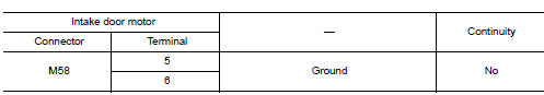
5.Check intake door motor PBR feedback signal circuit for short
Check continuity between intake door motor harness connector and ground.
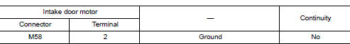
Is the inspection result normal? Yes >> go to 6.
No >> repair harness or connector.
6.Check intake door motor PBR
Check intake door motor pbr. Refer to hac-81, "component inspection (pbr)".
Is the inspection result normal? Yes >> replace a/c auto amp. Refer to hac-105, "removal and installation".
No >> replace intake door motor. Refer to hac-112, "intake door motor : removal and installation".
7.Check intake door motor pbr power supply circuit for open
- Turn ignition switch OFF
- Disconnect a/c auto amp. Connector.
- Check continuity between intake door motor harness connector and A/C auto amp. harness connector.
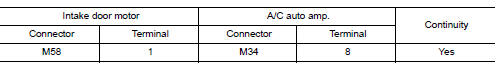
Is the inspection result normal? Yes >> replace a/c auto amp. Refer to hac-105, "removal and installation".
No >> repair harness or connector.
8.Check intake door motor drive signal circuit for open
- Turn ignition switch OFF.
- Disconnect intake door motor connector, and a/c auto amp. Connector.
- Check continuity between intake door motor harness connector and A/C auto amp. harness connector
Is the inspection result normal? Yes >> go to 9.
No >> repair harness or connector.
9.Check intake door motor drive signal circuit for short
Check continuity between intake door motor harness connector and ground.
Is the inspection result normal? Yes >> go to 10.
No >> repair harness or connector.
10.Check intake door motor
- Turn ignition switch off.
- Check intake door motor. Refer to hac-82, "component inspection (motor)".
Is the inspection result normal? YES >> GO TO 11.
NO >> Replace intake door motor. Refer to HAC-112, "INTAKE DOOR MOTOR : Removal and Installation".
11.Check installation of intake door motor system
Check intake door motor system is properly installed. Refer to HAC-111, "Exploded View".
Is the inspection result normal? YES >> Replace A/C auto amp. Refer to HAC-105, "Removal and Installation".
NO >> Repair or replace malfunctioning parts.
Component Inspection (PBR)
1.Check intake door motor PBR
Check resistance between intake door motor terminals.
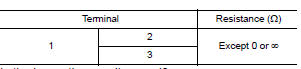
Is the inspection result normal? YES >> Inspection End.
NO >> Replace intake door motor. Refer to HAC-112, "INTAKE DOOR MOTOR : Removal and Installation".
Component Inspection (Motor)
1.Check intake door motor
Supply intake door motor terminals with battery voltage and check by visually and operation sound that intake door motor operates.
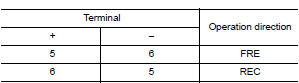
Is the inspection result normal? Yes >> inspection end.
No >> replace intake door motor. Refer to hac-112, "intake door motor : removal and installation".
 Basic inspection
DIAGNOSIS AND REPAIR WORKFLOW
Work Flow
OVERALL SEQUENCE
DETAILED FLOW
1.INTERVIEW CUSTOMER
Interview the customer to obtain as much information as possible about the
conditions and environ ...
 Power supply and ground circuit
A/C AUTO AMP
A/C AUTO AMP. : Diagnosis Procedure
Regarding Wiring Diagram information, refer to HAC-41, "Wiring Diagram".
1.CHECK FUSE
Check fuses [No. 5, 8 and 21, located in the fuse b ...
Other materials:
Precaution
Precaution for Supplemental Restraint System (SRS) "AIR BAG"
and "SEAT BELT PRE-TENSIONER"
The Supplemental Restraint System such as “AIR BAG” and “SEAT
BELT PRE-TENSIONER”, used along
with a front seat belt, helps to reduce the risk or severity of injur ...
U1000 Can comm circuit
Description
CAN (Controller Area Network) is a serial communication line for real-time
application. It is an on-vehicle multiplex
communication line with high data communication speed and excellent malfunction
detection ability.
Many electronic control units are equipped onto a vehicle, an ...
Tow Truck Towing
NISSAN recommends that vehicle be towed with driving (front) wheels off the
ground or that a dolly be used.
CVT: Continuously Variable Transmission
M/T: Manual transmission
CAUTION:
All applicable state or Provincial laws and local laws regarding
the towing operation must be ...
