Nissan Sentra Service Manual: Door lock actuator
Driver side
Driver side : component function check
1.CHECK FUNCTION
- Select DOOR LOCK of BCM using CONSULT.
- Select DOOR LOCK in ACTIVE TEST mode.
- Touch ALL LOCK or ALL UNLK to check that it works normally.
Is the inspection result normal? YES >> Door lock actuator is OK.
NO >> Refer to DLK-92, "DRIVER SIDE : Diagnosis Procedure".
Driver side : diagnosis procedure
Regarding Wiring Diagram information, refer to DLK-41, "Wiring Diagram".
1.Check door lock actuator input signal
- Turn ignition switch OFF.
- Disconnect front door lock actuator LH connector
- Check voltage between front door lock actuator LH harness connector and ground.
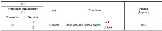
Is the inspection result normal? Yes >> replace front door lock actuator lh .
No >> go to 2.
2.Check door lock actuator circuit
- Disconnect BCM connector and all door lock actuator connectors.
- Check continuity between bcm harness connector and front door lock actuator lh harness connector.
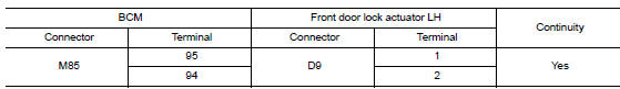
- Check continuity between bcm harness connector and ground.
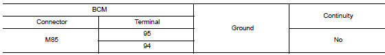
Is the inspection result normal? YES >> GO TO 3.
NO >> Repair or replace harness.
3.Check bcm output signal
- Connect bcm connector.
- Check voltage between front door lock actuator lh harness connector and ground.
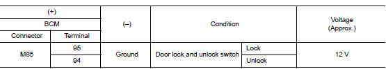
Is the inspection result normal? Yes >> check for internal short of each door lock actuator.
No >> replace bcm. Refer to bcs-73, "removal and installation".
Passenger side
Passenger side : component function check
1.Check function
- Select DOOR LOCK of BCM using CONSULT.
- Select DOOR LOCK in ACTIVE TEST mode.
- Touch all lock or all unlk to check that it works normally.
Is the inspection result normal? Yes >> door lock actuator is ok.
No >> refer to dlk-93, "passenger side : diagnosis procedure".
Passenger side : diagnosis procedure
Regarding wiring diagram information, refer to dlk-41, "wiring diagram".
1.Check door lock actuator input signal
- Turn ignition switch OFF.
- Disconnect front door lock actuator rh connector.
- Check voltage between front door lock actuator RH harness connector and ground.
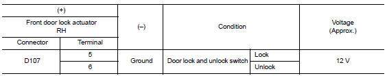
Is the inspection result normal? YES >> Replace front door lock actuator (RH).
NO >> GO TO 2.
2.Check door lock actuator circuit
- Disconnect bcm connector and all door lock actuators.
- Check continuity between bcm harness connector and front door lock actuator rh harness connector.
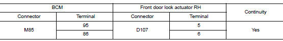
- Check continuity between bcm harness connector and ground.
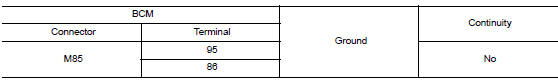
Is the inspection result normal? Yes >> go to 3.
No >> repair or replace harness.
3.Check bcm output signal
- Connect bcm connector.
- Check voltage between front door lock actuator rh harness connector and ground.
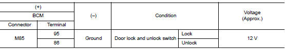
Is the inspection result normal? Yes >> check for internal short of each door lock actuator.
No >> replace bcm. Refer to bcs-73, "removal and installation".
Rear lh
Rear lh : component function check
1.Check function
- Select door lock of bcm using consult.
- Select DOOR LOCK in ACTIVE TEST mode.
- Touch all lock or all unlk to check that it works normally.
Is the inspection result normal? Yes >> door lock actuator is ok.
No >> refer to dlk-94, "rear lh : diagnosis procedure".
Rear lh : diagnosis procedure
Regarding Wiring Diagram information, refer to DLK-41, "Wiring Diagram".
1.Check door lock actuator input signal
- Turn ignition switch off.
- Disconnect rear door lock actuator lh connector.
- Check voltage between rear door lock actuator lh harness connector and ground.
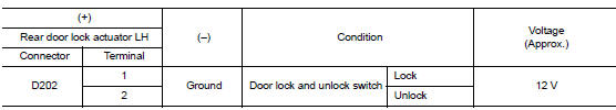
Is the inspection result normal? Yes >> replace rear door lock actuator lh.
No >> go to 2.
2.Check door lock actuator circuit
- Disconnect bcm connector and all door lock actuator connectors.
- Check continuity between bcm harness connector and rear door lock actuator lh harness connector.
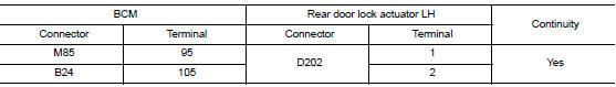
- Check continuity between bcm harness connector and ground.
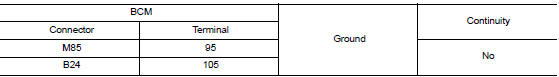
Is the inspection result normal? YES >> GO TO 3.
NO >> Repair or replace harness.
3.Check bcm output signal
- Connect BCM connector.
- Check voltage between rear door lock actuator LH harness connector and ground.
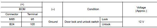
Is the inspection result normal? Yes >> check for internal short of each door lock actuator.
No >> replace bcm. Refer to bcs-73, "removal and installation".
Rear RH
REAR RH : Component Function Check
1.Check function
- Select door lock of bcm using consult.
- Select door lock in active test mode.
- Touch all lock or all unlk to check that it works normally.
Is the inspection result normal? Yes >> door lock actuator is ok.
No >> refer to dlk-95, "rear rh : diagnosis procedure".
REAR RH : Diagnosis Procedure
Regarding wiring diagram information, refer to dlk-41, "wiring diagram".
1.Check door lock actuator input signal
- Turn ignition switch off.
- Disconnect rear door lock actuator RH connector.
- Check voltage between rear door lock actuator rh harness connector and ground.
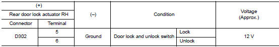
Is the inspection result normal? Yes >> replace rear door lock actuator rh.
No >> go to 2.
2.Check door lock actuator circuit
- Disconnect BCM connector and all door lock actuator connectors.
- Check continuity between bcm harness connector and rear door lock actuator rh harness connector.
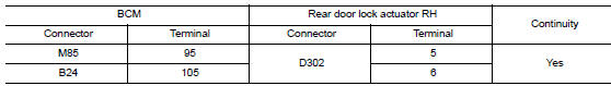
- Check continuity between bcm harness connector and ground.
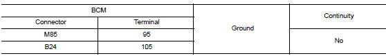
Is the inspection result normal? Yes >> go to 3.
No >> repair or replace harness.
3.Check bcm output signal
- Connect bcm connector.
- Check voltage between rear door lock actuator rh harness connector and ground.
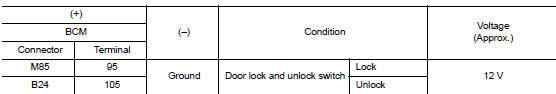
Is the inspection result normal? Yes >> check for internal short of each door lock actuator.
No >> replace bcm. Refer to bcs-73, "removal and installation".
 Power supply and ground circuit
Diagnosis procedure
Regarding wiring diagram information, refer to bcs-51, "wiring diagram".
1.Check fuses and fusible link
Check that the following fuses and fusible link are not blown.
...
 Door lock and unlock switch
Component function check
1.Check function
Select door lock of bcm using consult.
Select cdl lock sw, cdl unlock sw in data monitor mode.
Check that the function operates normally according to ...
Other materials:
Removal and installation
EPS control unit
Exploded View
Steering column assembly
EPS control unit
Bracket plate
Front
Removal and Installation
REMOVAL
CAUTION:
Disconnect battery negative terminal before starting
operations.
Do not shock EPS control unit, e.g. drop or hit.
Do not ...
Vehicle loading information
WARNING
It is extremely dangerous to ride
in a cargo area inside a vehicle. In
a collision, people riding in these
areas are more likely to be seriously
injured or killed.
Do not allow people to ride in any
area of your vehicle that is not
equipped with seats a ...
Ignition coil
Exploded View
Ignition coil
Spark plug
Rocker cover
Removal and Installation
REMOVAL
Remove the engine room cover. Refer to EM-24, "Exploded View".
Disconnect the harness connector from the ignition coil.
Remove the ignition coil.
CAUTION:
Do not drop or shock i ...
