Nissan Sentra Service Manual: Removal and installation
EPS control unit
Exploded View
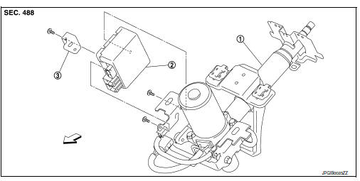
- Steering column assembly
- EPS control unit
- Bracket plate
 Front
Front
Removal and Installation
REMOVAL
CAUTION:
-
Disconnect battery negative terminal before starting operations.
-
Do not shock EPS control unit, e.g. drop or hit.
-
Do not get EPS control unit wet with water or other liquid. Also, do not give EPS control unit a radical temperature change to avoid getting water drops.
-
Do not disassemble or remodel EPS control unit, EPS motor, torque sensor, harness and harness connectors.
-
Remove steering column assembly. Refer to ST-12, "Removal and Installation".
-
Disconnect EPS motor harness connector
CAUTION:
Hold and pull the harness connector housing, not pulling harness, when disconnecting harness connectors. Also, do not grip, collapse or apply excessive force to the harness connector
-
Remove EPS control unit from steering column assembly.
-
Remove bracket plate from EPS control unit.
INSTALLATION
Installation is in the reverse order of removal.
-
Check that harness is not damaged when installing EPS control unit. Also, check that EPS control unit is installed without pinching harness or trapping foreign materials.
-
After installing steering column assembly, perform self-diagnosis with CONSULT to ensure correct operation.
Refer to STC-10, "CONSULT Function".
 Unbalance steering wheel turning force (torque variation)
Description
Unbalance steering wheel turning force (torque variation).
Diagnosis Procedure
1.PERFORM SELF-DIAGNOSIS
With CONSULT
Turn the ignition switch OFF to ON.
Perform EPS self- ...
 Restraints
...
Other materials:
ECU diagnosis information
EPS control unit
Reference Value
VALUES ON THE DIAGNOSIS TOOL
The following table includes information (items) inapplicable to
this vehicle. For information (items) applicable
to this vehicle, refer to CONSULT display items.
CAUTION:
The output signal indicates the EPS control unit
calcula ...
Wiring diagram
Nvis (nissan vehicle immobilizer system-
nats)
Wiring Diagram
Vehicle security system
Wiring diagram
...
Periodic maintenance
REAR WHEEL HUB
Inspection
COMPONENT PART
Check the mounting conditions (looseness, back lash) of each component and
component conditions (wear,
damage) are normal.
WHEEL HUB ASSEMBLY (BEARING-INTEGRATED TYPE)
Check the following items, and replace the part it necessary.
Move wheel hub as ...
