Nissan Sentra Service Manual: DTC/circuit diagnosis
U1000 CAN COMM CIRCUIT
Description
Refer to lan-7, "can communication system : system description".
Dtc logic
Dtc detection logic
Note:
U1000 can be set if a module harness was disconnected and reconnected, perhaps during a repair. Confirm that there are actual CAN diagnostic symptoms and a present DTC by performing the Self Diagnostic Result procedure.
| Consult display | Dtc detection condition | Possible cause |
| Can comm circuit [u1000] | When any listed module cannot communicate with CAN communication signal continuously for 2 seconds or more with ignition switch ON | In CAN communication system, any item (or
items) of the following listed below is malfunctioning.
|
Diagnosis procedure
1. Perform self diagnostic result
- Turn ignition switch on and wait for 2 seconds or more.
- Check “self- diag results”.
Is “can comm circuit” displayed? Yes >> perform can diagnosis as described in diagnosis section of consult operation manual.
No >> refer to gi-39, "intermittent incident".
U1010 control unit (can)
Dtc logic
Dtc detection logic
| Consult display | Dtc detection condition | Possible cause |
| CONTROL UNIT (CAN) [U1010] | BCM detected internal CAN communication circuit malfunction. | Bcm |
Diagnosis procedure
1.Replace BCM
When dtc “u1010” is detected, replace bcm.
>> Replace bcm. Refer to bcs-73, "removal and installation".
B2621 inside antenna
Dtc logic
Note:
The signal tech ii tool (j-50190) can be used to perform the following functions. Refer to the signal tech ii user guide for additional information.
- Check intelligent key relative signal strength
- Confirm vehicle Intelligent Key antenna signal strength
Dtc detection logic
| Dtc | Consult display description | Dtc detecting condition | Possible cause |
| B2621 | Inside antenna 1 | An excessive high or low voltage from inside antenna (instrument center) is sent to BCM |
|
Dtc confirmation procedure
1.Perform dtc confirmation procedure
- Select INTELLIGENT KEY of BCM using CONSULT.
- Select INSIDE ANT DIAGNOSIS in WORK SUPPORT mode.
- Perform inside key antenna (INSIDE ANT DIAGNOSIS) on WORK SUPPORT of INTELLIGENT KEY.
- Check BCM for DTC.
Is inside key antenna DTC detected? YES >> Refer to DLK-72, "Diagnosis Procedure".
NO >> Inside key antenna (instrument center) is OK.
Diagnosis procedure
Note:
The signal tech ii tool (j-50190) can be used to perform the following functions. Refer to the signal tech ii user guide for additional information.
- Check Intelligent Key relative signal strength
- Confirm vehicle intelligent key antenna signal strength
Regarding wiring diagram information, refer to dlk-49, "wiring diagram".
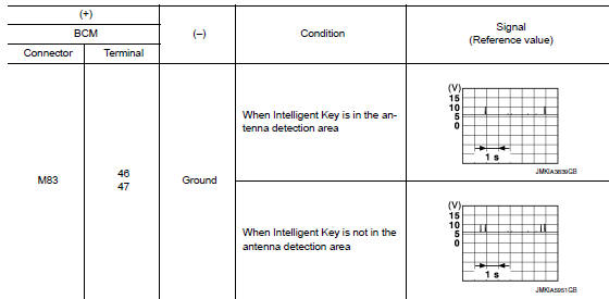
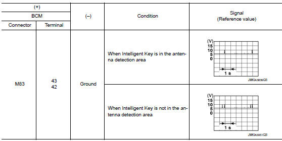
1.Check inside key antenna input signal 1
- Turn ignition switch on.
- Check signal between bcm harness connector and ground using oscilloscope.
Is the inspection result normal? Yes >> replace bcm. Refer to bcs-73, "removal and installation".
No >> go to 2.
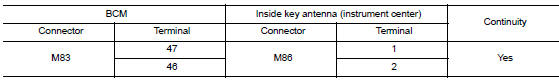
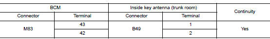
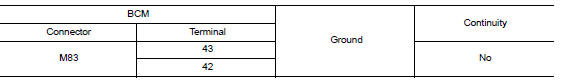
2.Check inside key antenna circuit
- Turn ignition switch OFF.
- Disconnect bcm connector and inside key antenna (instrument center) connector.
- Check continuity between bcm harness connector and inside key antenna (instrument center) harness connector.
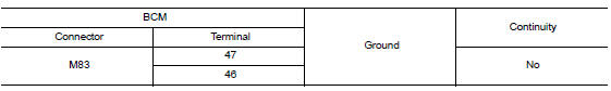
- Check continuity between bcm harness connector and ground.
Is the inspection result normal? Yes >> go to 3.
No >> repair or replace harness.
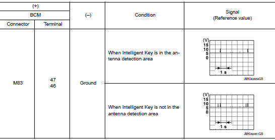
3.Check inside key antenna input signal 2
- Replace inside key antenna (instrument center). (New antenna or other antenna)
- Connect bcm connector and inside key antenna (instrument center) connector.
- Turn ignition switch on.
- Check signal between bcm harness connector and ground using oscilloscope
Is the inspection result normal? Yes >> replace inside key antenna (instrument center).
No >> replace bcm. Refer to bcs-73, "removal and installation".
B2622 inside antenna
Dtc logic
Note:
The Signal Tech II Tool (J-50190) can be used to perform the following functions. Refer to the Signal Tech II User Guide for additional information.
- Check intelligent key relative signal strength
- Confirm vehicle intelligent key antenna signal strength
Dtc detection logic
| Dtc | Consult display description | Dtc detecting condition | Possible cause |
| B2622 | INSIDE ANTENNA 2 | An excessive high or low voltage from inside antenna (console) is sent to bcm |
|
Dtc confirmation procedure
1.Perform dtc confirmation procedure
- Select intelligent key of bcm using consult.
- Select inside ant diagnosis in work support mode.
- Perform inside key antenna (inside ant diagnosis) on work support of intelligent key.
- Check BCM for DTC.
Is inside key antenna dtc detected? Yes >> refer to dlk-75, "diagnosis procedure".
No >> inside key antenna (console) is ok.
Diagnosis procedure
Note:
The Signal Tech II Tool (J-50190) can be used to perform the following functions. Refer to the Signal Tech II User Guide for additional information.
- Check intelligent key relative signal strength
- Confirm vehicle Intelligent Key antenna signal strength
Regarding wiring diagram information, refer to dlk-49, "wiring diagram".
1.Check inside key antenna input signal 1
- Turn ignition switch ON.
- Check signal between bcm harness connector and ground using oscilloscope.
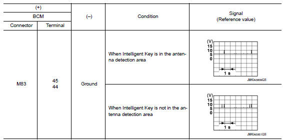
Is the inspection result normal? YES >> Replace BCM. Refer to BCS-73, "Removal and Installation".
NO >> GO TO 2.
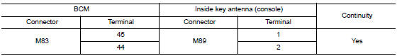
2.Check inside key antenna circuit
- Turn ignition switch OFF.
- Disconnect BCM connector and inside key antenna (console) connector
- Check continuity between bcm harness connector and inside key antenna (console) harness connector.
- Check continuity between bcm harness connector and ground.
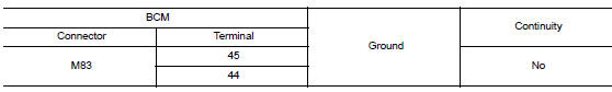
Is the inspection result normal? YES >> GO TO 3.
NO >> Repair or replace harness.
3.Check inside key antenna input signal 2
- Replace inside key antenna (console). (New antenna or other antenna)
- Connect bcm connector and inside key antenna (console) connector.
- Turn ignition switch ON.
- Check signal between BCM harness connector and ground using oscilloscope.
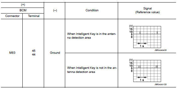
Is the inspection result normal? Yes >> replace inside key antenna (console).
No >> replace bcm. Refer to bcs-73, "removal and installation".
B2623 inside antenna
Dtc logic
Note:
The Signal Tech II Tool (J-50190) can be used to perform the following functions. Refer to the Signal Tech II User Guide for additional information.
- Check intelligent key relative signal strength
- Confirm vehicle Intelligent Key antenna signal strength
Dtc detection logic
| Dtc | Consult display description | Dtc detecting condition | Possible cause |
| B2623 | INSIDE ANTENNA 3 | An excessive high or low voltage from inside antenna (trunk room) is sent to bcm |
|
Dtc confirmation procedure
1.Perform dtc confirmation procedure
- Select INTELLIGENT KEY of BCM using CONSULT.
- Select inside ant diagnosis in work support mode.
- Perform inside key antenna (inside ant diagnosis) on work support of intelligent key.
- Check BCM for DTC.
Is inside key antenna dtc detected? Yes >> refer to dlk-78, "diagnosis procedure".
No >> inside key antenna (trunk room) is ok.
Diagnosis procedure
Note:
The signal tech ii tool (j-50190) can be used to perform the following functions. Refer to the signal tech ii user guide for additional information.
- Check intelligent key relative signal strength
- Confirm vehicle Intelligent Key antenna signal strength
Regarding Wiring Diagram information, refer to DLK-49, "Wiring Diagram".
1.Check inside key antenna input signal 1
- Turn ignition switch ON.
- Check signal between bcm harness connector and ground using oscilloscope.
Is the inspection result normal? Yes >> replace bcm. Refer to bcs-73, "removal and installation".
No >> go to 2.
2.Check inside key antenna circuit
- Turn ignition switch off.
- Disconnect BCM connector and inside key antenna (trunk room) connector.
- Check continuity between BCM harness connector and inside key antenna (trunk room) harness connector.
- Check continuity between BCM harness connector and ground.
Is the inspection result normal? Yes >> go to 3.
No >> repair or replace harness.
3.Check inside key antenna input signal 2
- Replace inside key antenna (trunk room). (New antenna or other antenna)
- Connect bcm connector and inside key antenna (trunk room) connector.
- Turn ignition switch ON.
- Check signal between bcm harness connector and ground using oscilloscope.
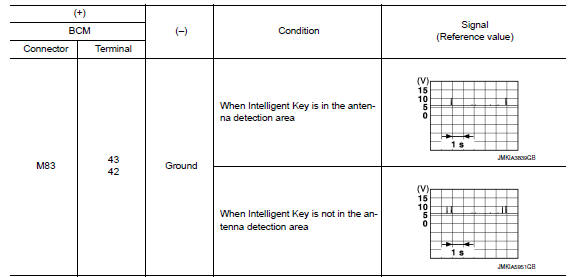
Is the inspection result normal? Yes >> replace inside key antenna (trunk room).
No >> replace bcm. Refer to bcs-73, "removal and installation".
B2626 outside antenna
Dtc logic
Note:
The signal tech ii tool (j-50190) can be used to perform the following functions. Refer to the signal tech ii user guide for additional information.
- Check Intelligent Key relative signal strength
- Confirm vehicle intelligent key antenna signal strength
Dtc detection logic
| DTC | CONSULT display description | DTC detecting condition | Possible cause |
| B2626 | B2626 OUTSIDE ANTENNA 1 | An excessive high or low voltage from outside key antenna (driver side) is sent to BCM |
|
DTC CONFIRMATION PROCEDURE
1.PERFORM DTC CONFIRMATION PROCEDURE
- Turn ignition switch ON.
- Check “Self Diagnostic Result” mode of “BCM” using CONSULT.
Is DTC detected? YES >> Refer to DLK-81, "Diagnosis Procedure".
NO >> Outside key antenna (driver side) is OK.
Diagnosis Procedure
NOTE:
The Signal Tech II Tool (J-50190) can be used to perform the following functions. Refer to the Signal Tech II User Guide for additional information.
- Check Intelligent Key relative signal strength
- Confirm vehicle Intelligent Key antenna signal strength
Regarding Wiring Diagram information, refer to DLK-49, "Wiring Diagram".
1.Check outside key antenna input signal 1
- Turn ignition switch ON.
- Check signal between BCM harness connector and ground using oscilloscope.
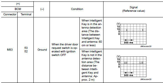
Is the inspection result normal? YES >> Replace BCM. Refer to BCS-73, "Removal and Installation".
NO >> GO TO 2.
2.Check outside key antenna circuit
- Turn ignition switch OFF.
- Disconnect bcm connector and outside key antenna (driver side) connector.
- Check continuity between bcm harness connector and outside key antenna (driver side) harness connector.
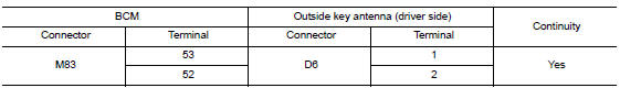
- Check continuity between bcm harness connector and ground.
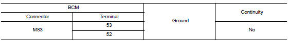
Is the inspection result normal? Yes >> go to 3.
No >> repair or replace harness.
3.Check outside key antenna input signal 2
- Replace outside key antenna (driver side). (New antenna or other antenna)
- Connect bcm connector and outside key antenna (driver side) connector.
- Turn ignition switch on.
- Check signal between bcm harness connector and ground using oscilloscope.
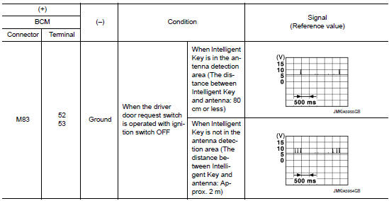
Is the inspection result normal? Yes >> replace outside key antenna (driver side).
No >> replace bcm. Refer to bcs-73, "removal and installation".
B2627 outside antenna
Dtc logic
Note:
The Signal Tech II Tool (J-50190) can be used to perform the following functions. Refer to the Signal Tech II User Guide for additional information.
- Check intelligent key relative signal strength
- Confirm vehicle intelligent key antenna signal strength
Dtc detection logic
| Dtc | Consult display description | Dtc detecting condition | Possible cause |
| B2627 | Outside antenna 2 | An excessive high or low voltage from outside key antenna (passenger side ) is sent to BCM |
|
Dtc confirmation procedure
1.Perform dtc confirmation procedure
- Turn ignition switch on.
- Check self diagnostic result mode of bcm using consult.
Is outside key antenna dtc detected? Yes >> refer to dlk-84, "diagnosis procedure".
No >> outside key antenna (passenger side) is ok.
Diagnosis procedure
Note:
The signal tech ii tool (j-50190) can be used to perform the following functions. Refer to the signal tech ii user guide for additional information.
- Check intelligent key relative signal strength
- Confirm vehicle intelligent key antenna signal strength
Regarding wiring diagram information, refer to dlk-49, "wiring diagram".
1.Check outside key antenna input signal 1
- Turn ignition switch ON.
- Check signal between bcm harness connector and ground using oscilloscope.
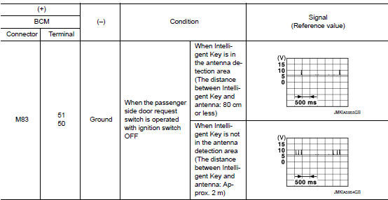
Is the inspection result normal? Yes >> replace bcm. Refer to bcs-73, "removal and installation".
No >> go to 2.
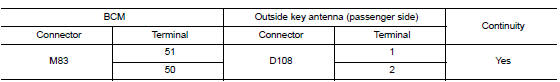
2.Check outside key antenna circuit
- Turn ignition switch OFF.
- Disconnect BCM connector and outside key antenna (passenger side) connector.
- Check continuity between bcm harness connector and outside key antenna (passenger side) harness connector.
- Check continuity between bcm harness connector and ground.
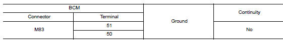
Is the inspection result normal? Yes >> go to 3.
No >> repair or replace harness.
3.Check outside key antenna input signal 2
- Replace outside key antenna (passenger side). (New antenna or other antenna)
- Connect bcm connector and outside key antenna (passenger side) connector.
- Turn ignition switch on.
- Check signal between bcm harness connector and ground using oscilloscope.
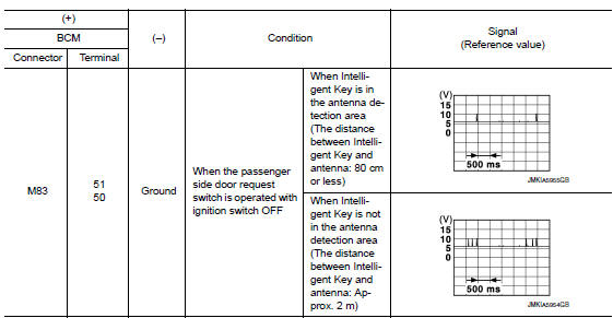
Is the inspection result normal? Yes >> replace outside key antenna (passenger side).
No >> replace bcm. Refer to bcs-73, "removal and installation".
B2628 outside antenna
Dtc logic
Note:
The Signal Tech II Tool (J-50190) can be used to perform the following functions. Refer to the Signal Tech II User Guide for additional information.
- Check intelligent key relative signal strength
- Confirm vehicle intelligent key antenna signal strength
Dtc detection logic
| Dtc | Consult display description | Dtc detecting condition | Possible cause |
| B2628 | OUTSIDE ANTENNA 3 | An excessive high or low voltage from outside key antenna (rear bumper) is sent to bcm |
|
Dtc confirmation procedure
1.Perform dtc confirmation procedure
- Turn ignition switch on.
- Check Self Diagnostic Result mode of BCM using CONSULT.
Is outside key antenna dtc detected? Yes >> refer to dlk-87, "diagnosis procedure".
No >> outside key antenna (rear bumper) is ok.
Diagnosis procedure
Note:
The signal tech ii tool (j-50190) can be used to perform the following functions. Refer to the signal tech ii user guide for additional information.
- Check intelligent key relative signal strength
- Confirm vehicle intelligent key antenna signal strength
Regarding wiring diagram information, refer to dlk-49, "wiring diagram".
1.Check outside key antenna input signal 1
- Turn ignition switch ON.
- Check signal between BCM harness connector and ground using oscilloscope.
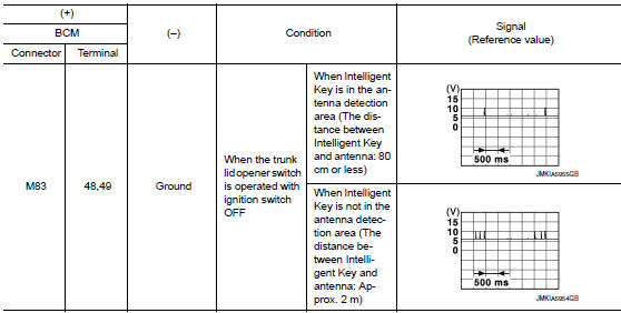
Is the inspection result normal? Yes >> replace bcm. Refer to bcs-73, "removal and installation".
No >> go to 2.
2.Check outside key antenna circuit
- Turn ignition switch off.
- Disconnect bcm connector and outside key antenna (rear bumper) connector.
- Check continuity between bcm harness connector and outside key antenna (rear bumper) harness connector.
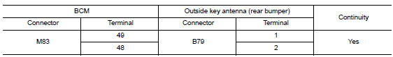
- Check continuity between BCM harness connector and ground.
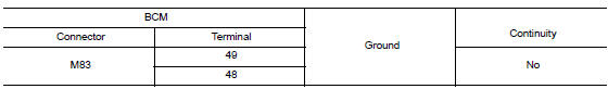
Is the inspection result normal? Yes >> go to 3.
No >> repair or replace harness.
3.Check outside key antenna input signal 2
- Replace outside key antenna (rear bumper). (New antenna or other antenna)
- Connect bcm and outside key antenna (rear bumper) connector.
- Turn ignition switch on.
- Check signal between BCM harness connector and ground using oscilloscope.
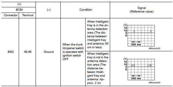
Is the inspection result normal? Yes >> replace outside key antenna (rear bumper).
No >> replace bcm. Refer to bcs-73, "removal and installation".
 Basic inspection
Diagnosis and repair work flow
Work flow
OVERALL SEQUENCE
Detailed flow
1.Get information for symptom
Get detailed information from the customer about the symptom (the
condition and the ...
 Power supply and ground circuit
Diagnosis procedure
Regarding wiring diagram information, refer to bcs-51, "wiring diagram".
1.Check fuses and fusible link
Check that the following fuses and fusible link are not blown.
...
Other materials:
Trouble diagnosis - specification
value
Description
The specification (SP) value indicates the tolerance of the value that is
displayed in “SPEC” of “DATA MONITOR”
mode of CONSULT during normal operation of the Engine Control System. When the
value in “SPEC” of
“DATA MONITOR” mode is within t ...
A-bag branch line circuit
Diagnosis procedure
Warning:
Always observe the following items for preventing accidental
activation.
Before servicing, turn ignition switch off, disconnect battery
negative terminal, and wait 3 minutes
or more. (To discharge backup capacitor.)
Never use unspecified tester or other me ...
Main line between ipdm-e and dlc
circuit
Diagnosis procedure
1.Check connector
Turn the ignition switch off.
Disconnect the battery cable from the negative terminal.
Check the following terminals and connectors for damage, bend and loose
connection (connector side
and harness side).
Harness connector E4
Harness connec ...
