Nissan Sentra Service Manual: Ecu diagnosis information
ECM
Reference Value
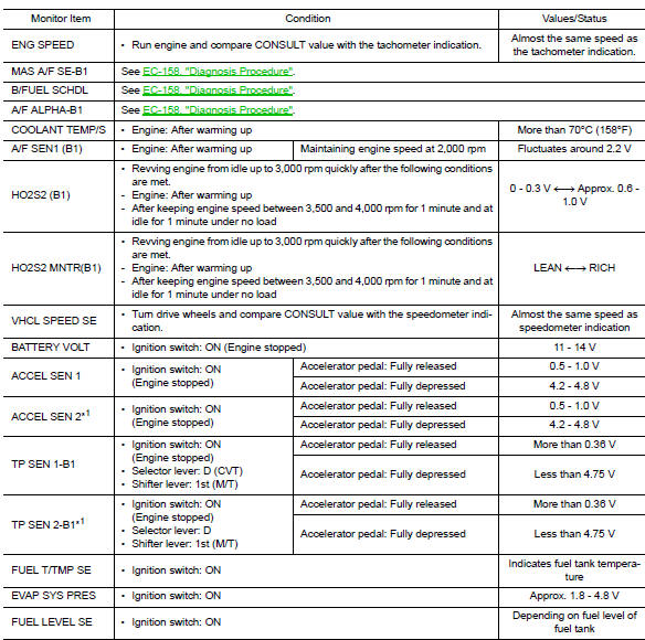
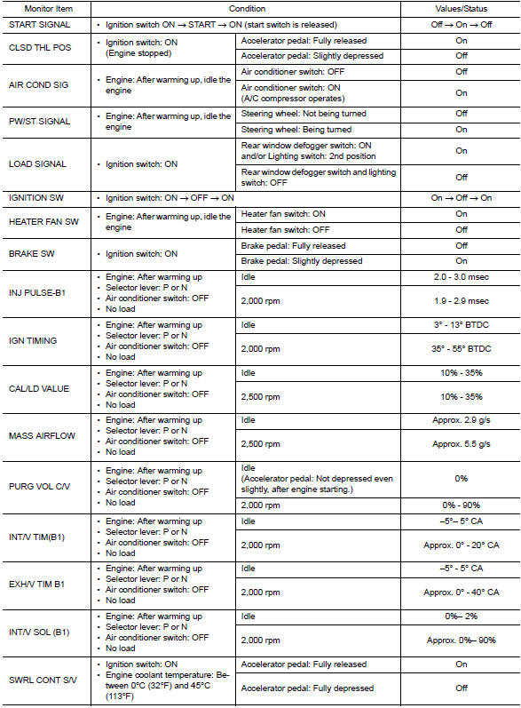
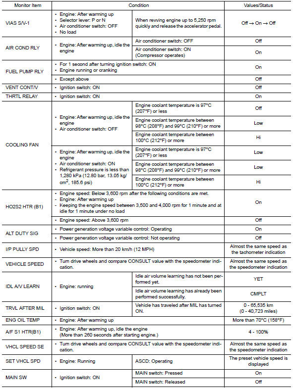
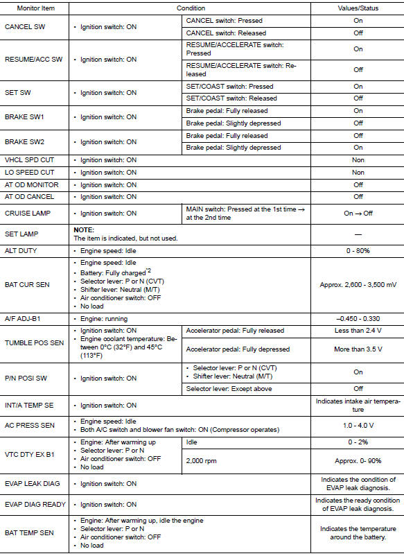
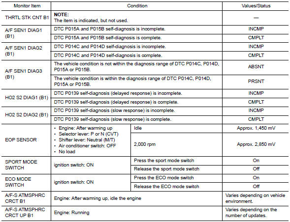
VALUES ON THE DIAGNOSIS TOOL
NOTE:
- The following table includes information (items) inapplicable to this vehicle. For information (items) applicable to this vehicle, refer to CONSULT display items.
- Numerical values in the following table are reference values.
- These values are input/output values that ECM receives/transmits and may differ from actual operations.
Example: The ignition timing shown by the timing light may differ from the ignition timing displayed on the data monitor. This occurs because the timing light shows a value calculated by ECM according to signals received from the cam shaft position sensor and other sensors related to ignition timing.
For outlines of following items, refer to EC-66, "CONSULT Function".
*1: Accelerator pedal position sensor 2 signal and throttle position sensor 2 signal are converted by ECM internally. Thus, they differ from ECM terminals voltage signal.
*2: Before measuring the voltage, confirm that the battery is fully charged. Refer to PG-4, "How to Handle Battery".
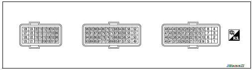
Terminal layout
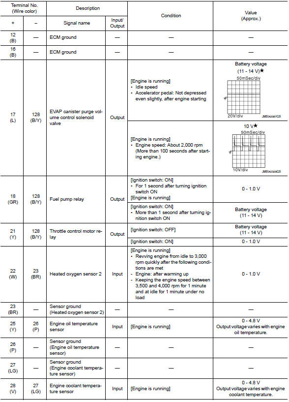
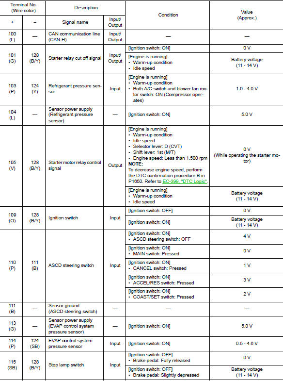
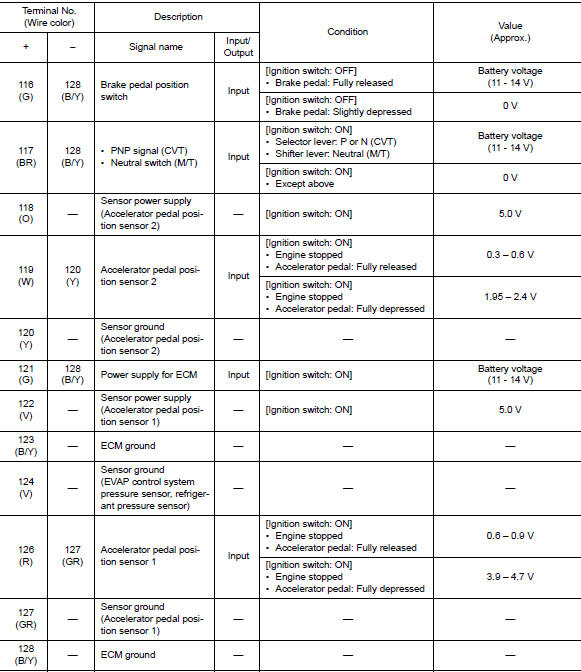
Physical values
NOTE:
- ECM is located in the engine room left side near battery.
- Specification data are reference values and are measured between each terminal and ground.
- Pulse signal is measured by CONSULT.
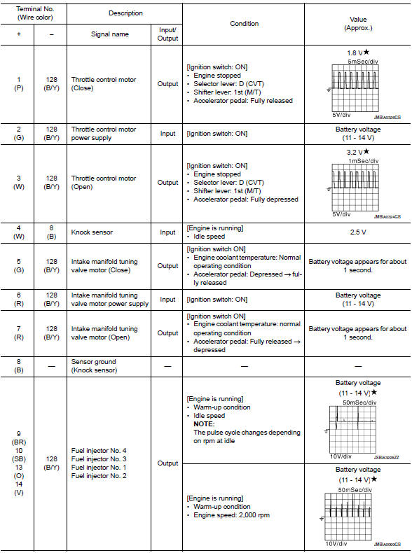
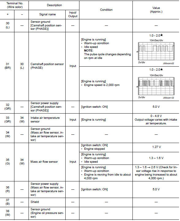
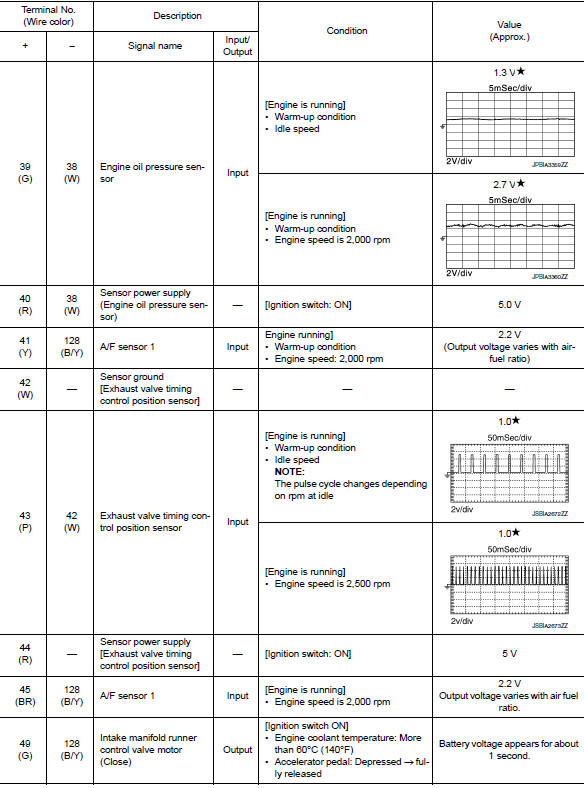
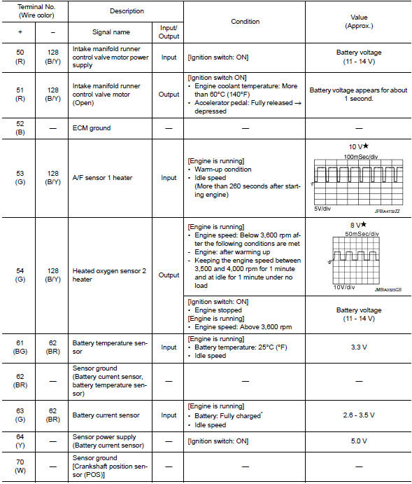
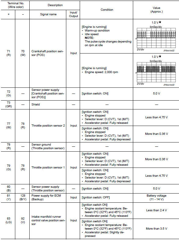
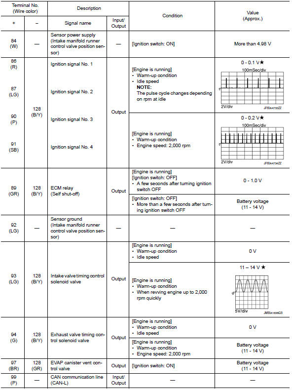
 Average voltage for pulse signal
(Actual pulse signal can be confirmed by oscilloscope.)
*Before measuring the terminal voltage, confirm that the battery is fully charged. Refer to PG-4, "How to Handle Battery".
Fail Safe
NON DTC RELATED ITEM
| Detected items | Engine operating condition in fail-safe mode | Remarks | Reference page |
| Malfunction indicator circuit | Engine speed will not rise more than 2,500 rpm due to the fuel cut | When there is an open circuit on MIL circuit, the ECM cannot warn
the
driver by lighting up MIL when there is malfunction on engine control
system.
Therefore, when electrical controlled throttle and part of ECM related diagnoses are continuously detected as NG for 5 trips, ECM warns the driver that engine control system malfunctions and MIL circuit is open by means of operating fail safe function. The fail safe function also operates when above diagnoses except MIL circuit are detected and demands the driver to repair the malfunction. |
EC-467, "Component Function Check" |
DTC RELATED ITEM
Description
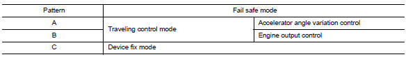
When a DTC is detected, ECM executes a mode (in the Fail-safe mode) applicable to the DTC. The fail-safe mode has the preset traveling control mode (accelerator angle variation and engine output limit) and device fix mode.
| Fail safe mode | Vehicle behavior | |
| Traveling control mode | Accelerator angle variation control | ECM controls the accelerator pedal depression speed to make it
slower than actual speed. This
causes a drop in accelerating performance and encourages the driver to
repair malfunction. NOTE: ECM does not control the accelerator pedal releasing speed. |
| Engine output control | ECM reduces the engine output, according to the rise in engine speed. This reduces the vehicle speed to encourage the driver to repair malfunction. | |
| Device fix mode |
|
|
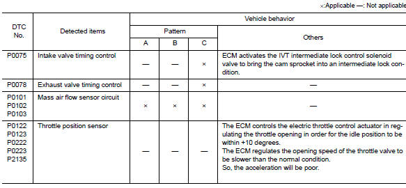
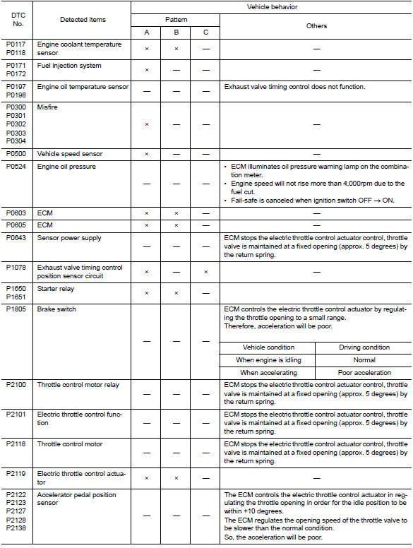
Fail Safe Pattern
Fail Safe List
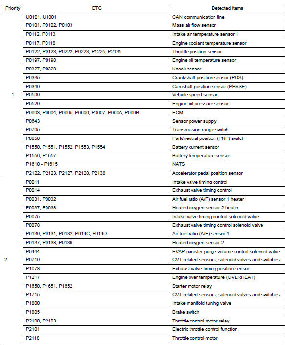
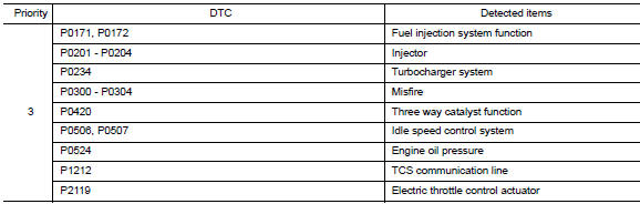
DTC Inspection Priority Chart
If some DTCs are displayed at the same time, perform inspections one by one based on the following priority chart.
DTC Index
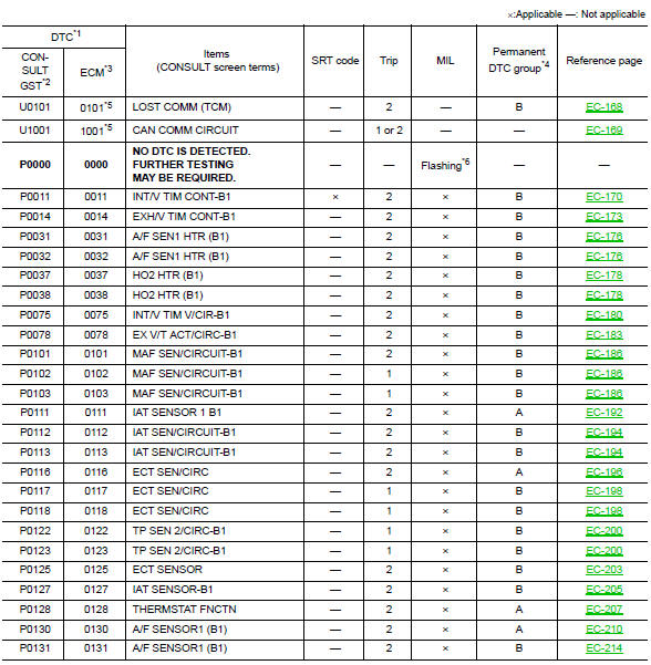
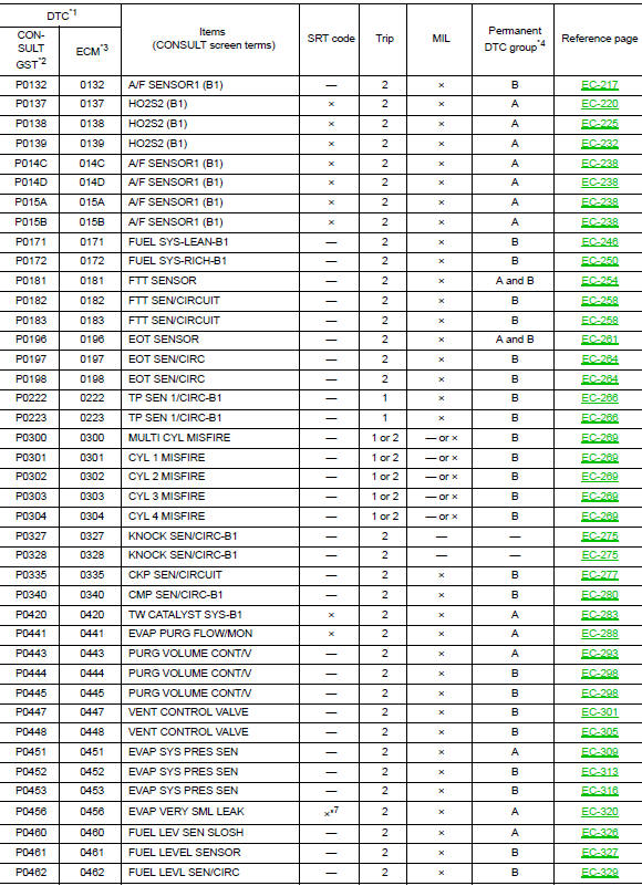
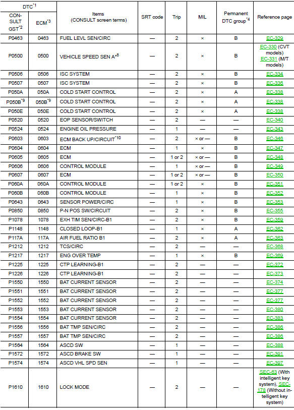
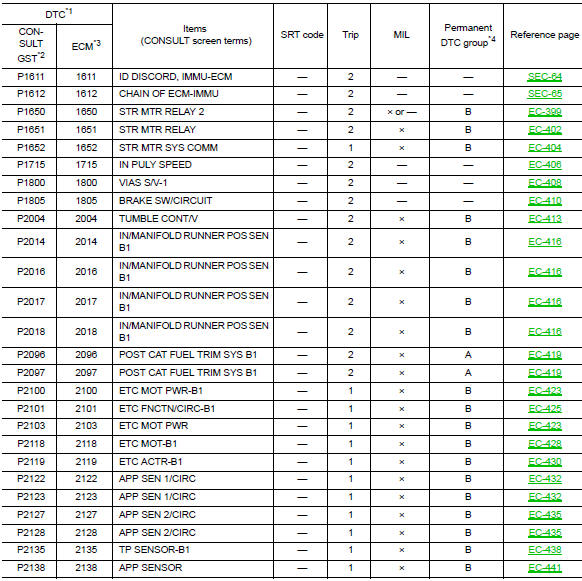
1*-1st trip DTC No. is the same as DTC No.
2*-This number is prescribed by SAE J1979/ ISO 15031-5.
3*-In Diagnostic Test Mode II (Self-diagnostic results), this number is controlled by NISSAN.
4*-Refer to EC-151, "Description".
5*-The trouble diagnosis for this DTC needs CONSULT
6*-When the ECM is in the mode that displays SRT status, MIL may blink. For details, Refer to EC-63, "On Board Diagnosis Function".
7*-SRT code will not be set if the self-diagnostic result is NG.
8*-When the fail-safe operations for both self-diagnoses occur, the MIL illuminates.
9*-For CALIFORNIA
10*-This self-diagnosis is not for ECM power supply circuit, even though “ECM BACK UP/CIRCUIT” is displayed on CONSULT screen.
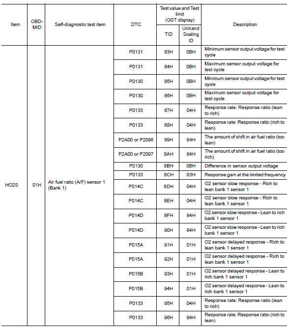
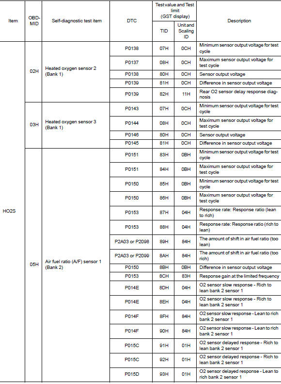
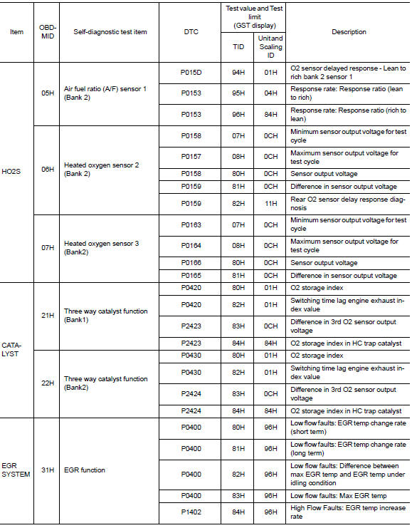
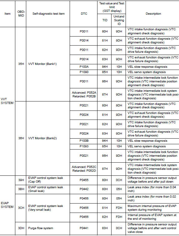
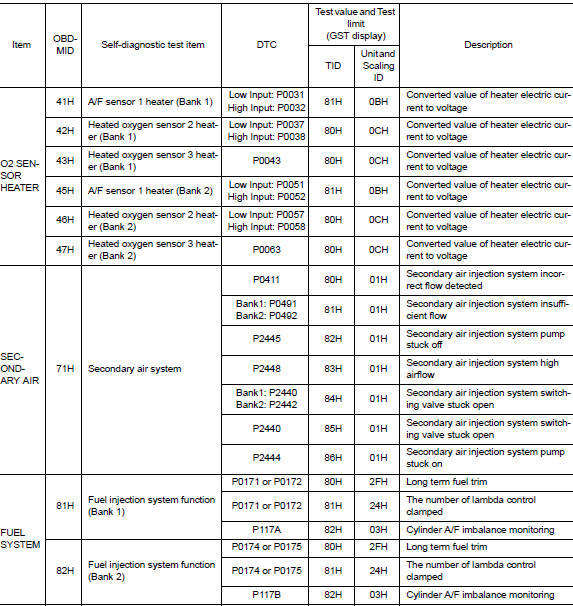
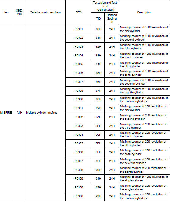
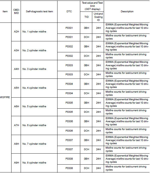
Test Value and Test Limit
The following is the information specified in Service $06 of SAE J1979/ISO 15031-5.
The test value is a parameter used to determine whether a system/circuit diagnostic test is OK or NG while being monitored by the ECM during self-diagnosis. The test limit is a reference value which is specified as the maximum or minimum value and is compared with the test value being monitored.
These data (test value and test limit) are specified by On Board Monitor ID (OBDMID), Test ID (TID), Unit and Scaling ID and can be displayed on the GST screen.
The items of the test value and test limit will be displayed with GST screen which items are provided by the ECM. (e.g., if bank 2 is not applied on this vehicle, only the items of bank 1 are displayed)
 Consult function
FUNCTION
Diagnostic test mode
Function
Self Diagnostic Results
Self-diagnostic results such as 1st trip DTC, DTCs and 1st trip
freeze frame data or freeze frame data
can ...
 Wiring diagram
Engine control system
Wiring Diagram
...
Other materials:
Wiper and washer fuse
Description
Diagnosis procedure
1. Check fuses
Check that the following fuses are not blown.
Is the fuse blown?
Yes >> replace the blown fuse after repairing the affected circuit.
No >> inspection end. ...
DTC/Circuit diagnosis
POSITION SWITCH
BACK-UP LAMP SWITCH
BACK-UP LAMP SWITCH : Component Inspection
1.CHECK BACK-UP LAMP SWITCH
Disconnect position switch harness connector. Refer to TM-21, "Removal
and Installation".
Check continuity between position switch terminals.
Is the inspection ...
Eps warning lamp does not turn on
Description
EPS warning lamp does not turn ON when turning ignition switch
ON from OFF. (Check the illumination of the
EPS warning lamp.)
Diagnosis Procedure
1.CHECK EPS WARNING LAMP
Perform the trouble diagnosis of EPS warning lamp. Refer to
STC-31, "Diagnosis Procedure".
Is ...
