Nissan Sentra Service Manual: Removal and installation
REAR WHEEL HUB
Exploded View - Drum brake
DRUM BRAKE
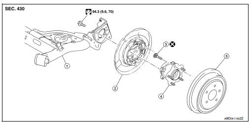
- Rear suspension beam
- Brake assembly
- Wheel stud
- Wheel hub assembly (Bearing-integrated type)
- Brake drum
Removal and Installation - Drum brake
REMOVAL
- Remove the wheel and tire using power tool. Refer to WT-47, "Removal and Installation".
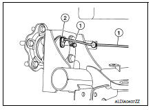
- Remove the rear wheel sensor bolt (1) and the rear wheel sensor (2). Refer to BRC-107, "REAR WHEEL SENSOR : Removal and Installation".
- Remove rear brake drum. Refer to BR-42, "Removal and Installation".
CAUTION:
Do not depress brake pedal while rear brake drum is removed.
- Remove the hub bolts and wheel hub assembly.
CAUTION:
Do not remove parking brake assembly. Protect it from falling.
INSTALLATION
Installation is in the reverse order of removal.
- Check that the wheel hub assembly operates smoothly
- Perform inspection after installation. Refer to RAX-8, "Inspection".
Exploded View - Disc brake
DISK BRAKE
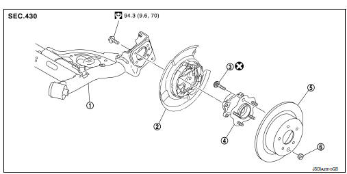
- Rear suspension beam
- Parking brake assembly
- Wheel stud
- Wheel hub assembly (Bearing-integrated type)
- Disc rotor
- Plug
Removal and Installation - Disc brake
REMOVAL
- Remove the wheel and tire using power tool. Refer to WT-47, "Removal and Installation".
- Remove the rear wheel sensor bolt (1) and the rear wheel sensor (2). Refer to BRC-107, "REAR WHEEL SENSOR : Removal and Installation".
- Remove the rear brake caliper assembly. Refer to BR-47, "BRAKE CALIPER ASSEMBLY : Removal and Installation".
CAUTION:
Do not depress brake pedal while rear brake assembly is removed.
- Remove the hub bolts and wheel hub assembly.
CAUTION:
Do not remove parking brake assembly. Protect it from falling.
INSTALLATION
Installation is in the reverse order of removal.
- Align the matching marks that have been made during removal when reusing the disc rotor.
- Check that the wheel hub assembly operates smoothly
- Perform inspection after installation. Refer to RAX-8, "Inspection".
Inspection
INSPECTION AFTER REMOVAL
Check the wheel hub assembly for wear, cracks, and damage. Replace if necessary.
INSPECTION AFTER INSTALLATION
- Check wheel sensor harness for proper connection. Refer to BRC-107, "REAR WHEEL SENSOR : Exploded View".
- Adjust parking brake operation (stroke). Refer to PB-4, "Inspection and Adjustment".
- Check wheel alignment. Refer to RSU-6, "Inspection".
 Periodic maintenance
REAR WHEEL HUB
Inspection
COMPONENT PART
Check the mounting conditions (looseness, back lash) of each component and
component conditions (wear,
damage) are normal.
WHEEL HUB ASSEMBLY (BEARING-I ...
 Service data and specifications (SDS)
Wheel Bearing
...
Other materials:
Precautions on cruise control
ACCEL/RES switch
COAST/SET switch
CANCEL switch
ON·OFF switch
If the cruise control system malfunctions, it
cancels automatically. The CRUISE indicator
light in the instrument panel then blinks to
warn the driver, see “Warnings/Indicator
Lights and Audible Reminders” ...
Removal and installation
Ipdm e/r
Exploded view
Ipdm e/r
Ipdm e/r cover a
Ipdm e/r cover b
Removal and installation
Caution:
Ipdm e/r integrated relays are not serviceable and must not be removed
from unit.
Removal
Remove inlet air duct (upper). Refer to em-25, "removal and
installation". ...
Front fog lamp
Removal and Installation
FOG LAMP
Removal
Position the fender protector aside. Refer to EXT-28, "FENDER PROTECTOR
: Removal and Installation
- Front Fender Protector".
Disconnect the harness connector from the front fog lamp.
Remove the screws and the front fog lamp.
Inst ...
