Nissan Sentra Service Manual: P099B Shift solenoid G
DTC Logic
DTC DETECTION LOGIC
| DTC | CONSULT screen terms (Trouble diagnosis content) | DTC detection condition | Possible causes |
| P099B | SHIFT SOLENOID G (Shift Solenoid G Control Circuit Low) | The TCM high clutch & reverse brake solenoid
valve current monitor reading is 200 mA or
less continuously for 200 msec or more under
the following diagnosis conditions: Diagnosis conditions
|
|
DTC CONFIRMATION PROCEDURE
1.PREPARATION BEFORE WORK
If another “DTC CONFIRMATION PROCEDURE” occurs just before, turn ignition switch OFF and wait for at least 10 seconds, then perform the next test.
>> GO TO 2.
2.CHECK DTC DETECTION
- Start the engine and wait for 5 seconds or more.
- Check the first trip DTC.
Is “P099B” detected? YES >> Go to TM-214, "Diagnosis Procedure".
NO >> INSPECTION END
Diagnosis Procedure
1.CHECK CIRCUIT BETWEEN TCM AND CVT UNIT
- Turn ignition switch OFF.
- Disconnect TCM connector and CVT unit connector.
- Check continuity between TCM harness connector terminal and ground.
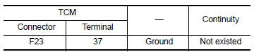
Is the inspection result normal? YES >> GO TO 2.
NO >> Repair or replace malfunctioning parts.
2.CHECK HIGH CLUTCH & REVERSE BRAKE SOLENOID VALVE
Check high clutch & reverse brake solenoid valve. Refer to TM-214, "Component Inspection".
Is the inspection result normal? YES >> Check intermittent incident. Refer to GI-39, "Intermittent Incident".
NO >> Repair or replace malfunctioning parts.
Component Inspection
1.CHECK HIGH CLUTCH & REVERSE BRAKE SOLENOID VALVE
Check resistance between CVT unit connector terminal and ground.
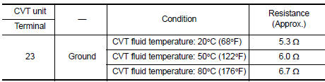
Is the inspection result normal? YES >> INSPECTION END
NO >> There is a malfunction of high & reverse brake solenoid valve. Replace transaxle assembly. Refer to TM-283, "Removal and Installation".
 P0999 Shift solenoid F
DTC Logic
DTC DETECTION LOGIC
DTC
CONSULT screen terms
(Trouble diagnosis content)
DTC detection condition
Possible causes
P0999
SHIFT SOLENOID F
(Shift Solenoid F ...
 P099C Shift solenoid G
DTC Logic
DTC
CONSULT screen terms
(Trouble diagnosis content)
DTC detection condition
Possible causes
P099C
SHIFT SOLENOID G
(Shift Solenoid G Control Circuit
H ...
Other materials:
Measurement of weights
Secure loose items to prevent weight
shifts that could affect the balance of your
vehicle. When the vehicle is loaded, drive
to a scale and weigh the front and the rear
wheels separately to determine axle
loads. Individual axle loads should not exceed
either of the gross axle weight ratings
( ...
Ecu diagnosis information
Av control unit
Reference value
TERMINAL LAYOUT
PHYSICAL VALUES
Dtc index
Bose speaker amp
Reference value
TERMINAL LAYOUT
PHYSICAL VALUES
...
Can communication
CAN COMMUNICATION : System Description
CAN (Controller Area Network) is a serial communication line for real time
application. It is an on-vehicle multiplex
communication line with high data communication speed and excellent error
detection ability. Many electronic
control units are equipped ...
