Nissan Sentra Service Manual: Power generation voltage variable control system operation inspection
Diagnosis Procedure
Regarding wiring diagram information. Refer to chg-9, "wiring diagram".
Caution:
When performing this inspection, always use a charged battery that has completed the battery inspection.
(When the charging rate of the battery is low, the response speed of the voltage change will become slow. This can cause an incorrect inspection.)
1.Check ecm (consult)
Perform ecm self-diagnosis with consult. Refer to ec-66, "consult function".
Self-diagnostic results content
No malfunction detected>> go to 2.
Malfunction detected>> check applicable parts, and repair or replace corresponding parts.
2.Check operation of power generation voltage variable control system
- Connect consult and start the engine.
- The selector lever is in “p” or “n” position and all of the electric loads and a/c, etc. Are turned off.
- Select “alternator duty” in “active test” of “engine”, and then check the value of “battery volt” monitor when duty value of “duty” is set to 40.0 %.
“Battery volt” 2 seconds after setting the duty value of “alternator duty” to 40.0 % : 12 - 13.6 V
- Check the value of “battery volt” monitor when duty value of “duty” is set to 80.0%.
“Battery volt” 20 seconds after setting the duty value of “alternator duty” to 80.0 % : +0.5 V or more against the value of “battery volt” monitor when duty value is 40.0 %
Is the inspection result normal? Yes >> inspection end.
No >> go to 3.
3.Check ipdm e/r (consult)
Perform ipdm e/r self-diagnosis with consult. Refer to pcs-10, "consult function (ipdm e/r)"
(with intelligent key system) or pcs-38, "consult function (ipdm e/r)" (without intelligent key system).
Is the inspection result normal? No malfunction detected>> go to 4.
Malfunction detected>> check applicable parts, and repair or replace corresponding parts.
4.Check harness between generator and ipdm e/r
- Turn ignition switch off.
- Disconnect generator connector and ipdm e/r connector.
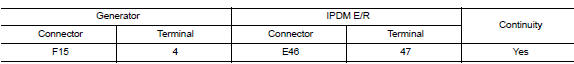
- Check continuity between generator harness connector and ipdm e/r harness connector.
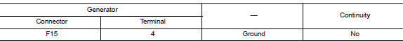
- Check continuity between generator harness connector and ground.
Is the inspection result normal? Yes >> replace ipdm e/r. Refer to pcs-30, "removal and installation".
No >> repair harness or connectors between ipdm e/r and generator.
 Charging system preliminary inspection
Diagnosis Procedure
1.CHECK BATTERY TERMINALS CONNECTION
Check if battery terminals are clean and tight.
Is the inspection result normal?
YES >> GO TO 2.
NO >> Repair battery term ...
 B terminal circuit
Description
“B” terminal circuit supplies power to charge the battery and to operate the
vehicles electrical system.
Diagnosis procedure
Regarding wiring diagram information. Refer to c ...
Other materials:
Ecu diagnosis information
Audio unit
Reference value
TERMINAL LAYOUT
PHYSICAL VALUES
Bose speaker amp
Reference value
TERMINAL LAYOUT
PHYSICAL VALUES
BluetoothВ® control unit
Reference value
TERMINAL LAYOUT
PHYSICAL VALUES
...
Exhaust gas (carbon monoxide)
WARNINGDo not breathe exhaust gases; they
contain colorless and odorless carbon
monoxide. Carbon monoxide is dangerous.
It can cause unconsciousness or
death.
If you suspect that exhaust fumes are
entering the vehicle, drive with all windows
fully open, and have ...
P1805 Brake switch
DTC Logic
DTC DETECTION LOGIC
DTC No.
CONSULT screen terms
(Trouble diagnosis content)
DTC detecting condition
Possible cause
P1805
BRAKE SW/CIRCUIT
(Brake switch circuit)
Stop lamp signal is not sent to ECM for extremely
long time while the vehicle is drivi ...
