Nissan Sentra Service Manual: P0744 Torque converter
DTC Logic
DTC DETECTION LOGIC
| DTC | CONSULT screen terms (Trouble diagnosis content) | DTC detection condition | Possible causes |
| P0744 | TORQUE CONVERTER (Torque converter clutch circuit intermittent) | The torque converter slip speed is at or above
a set value (40 rpm + (Vehicle speed / 2) continuously
for 30 seconds or more under the following
diagnosis conditions: Diagnosis conditions
|
|
DTC CONFIRMATION PROCEDURE
CAUTION:
Be careful of the driving speed.
1.PREPARATION BEFORE OPERATION 1
If another “DTC CONFIRMATION PROCEDURE” occurs just before, turn ignition switch OFF and wait for at least 10 seconds, then perform the next test.
>> GO TO 2.
2.PREPARATION BEFORE OPERATION 2
 With CONSULT
- Start the engine.
- Select “Data Monitor” in “TRANSMISSION”.
- Select “FLUID TEMP”.
- Confirm that the CVT fluid temperature is in the range below.
FLUID TEMP : 20В°C (68В°F) or more
 With GST
- Start the engine.
- Set the CVT fluid to 20В°C (68В°F) or more.
NOTE:
When the ambient temperature is 20В°C (68В°F), the CVT fluid usually increases to 50 to 80В°C (122 to 176В°F) with driving in an urban area for approximately 10 minutes.
Is the CVT fluid 20В°C (68В°F) or more? YES >> GO TO 3.
NO >> 1. Warm the transaxle.
2. GO TO 3.
3.CHECK DTC DETECTION
- Drive the vehicle.
- Maintain the following conditions for 40 seconds or more.
Selector lever : “D” position
Accelerator pedal position : 1.0/8 or more
Vehicle speed : 40 km/h (25 MPH) or more
- Stop the vehicle
- Check the first trip DTC.
Is “P0744” detected? YES >> Go to TM-189, "Diagnosis Procedure".
NO >> INSPECTION END
Diagnosis Procedure
1.CHECK LINE PRESSURE
Perform line pressure test. Refer to TM-149, "Work Procedure".
Is the inspection result normal? YES >> GO TO 2.
NO >> Repair or replace the malfunction items.
2.CHECK TORQUE CONVERTER CLUTCH SOLENOID VALVE
- Turn ignition switch OFF.
- Disconnect CVT unit connector.
- Check torque converter clutch solenoid valve. Refer to TM-189, "Component Inspection".
Is the inspection result normal? YES >> Check intermittent incident. Refer to GI-39, "Intermittent Incident".
NO >> Repair or replace the malfunction items.
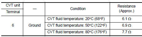
Component Inspection
1.CHECK TORQUE CONVERTER CLUTCH SOLENOID VALVE
Check resistance between CVT unit connector terminal and ground.
 Is the inspection
result normal?
YES >> INSPECTION END
NO >> There is a malfunction of torque converter clutch solenoid valve. Replace transaxle assembly.
Refer to TM-283, "Removal and Installation".
 P0743 Torque converter
DTC Logic
DTC DETECTION LOGIC
DTC
CONSULT screen terms
(Trouble diagnosis content)
DTC detection condition
Possible causes
P0743
TORQUE CONVERTER
(Torque Converter ...
 P0746 Pressure control solenoid A
DTC Logic
DTC DETECTION LOGIC
DTC
CONSULT screen terms
(Trouble diagnosis content)
DTC detection condition
Possible causes
P0746
PRESSURE CONTROL SOLENOID
A
(Pre ...
Other materials:
Front fog lamp circuit
Description
The ipdm e/r (intelligent power distribution module engine room) controls the
front fog lamp relay based on
inputs from the bcm over the can communication lines. When the front fog lamp
relay is energized, power
flows from the front fog lamp relay in the ipdm e/r to the front fog ...
Service data and specifications (SDS)
General Specifications
Clutch Pedal
Clutch Disc
Clutch Cover
...
P0998 Shift solenoid F
DTC Logic
DTC DETECTION LOGIC
DTC
CONSULT screen terms
(Trouble diagnosis content)
DTC detection condition
Possible causes
P0998
SHIFT SOLENOID F
(Shift Solenoid F Control Circuit
Low)
The TCM low brake solenoid valve current
monitor reading is 200 mA or ...
