Nissan Sentra Service Manual: P0746 Pressure control solenoid A
DTC Logic
DTC DETECTION LOGIC
| DTC | CONSULT screen terms (Trouble diagnosis content) | DTC detection condition | Possible causes |
| P0746 | PRESSURE CONTROL SOLENOID A (Pressure Control Solenoid A Performance/Stuck Off) | The detecting condition A or detection condition
B is detected twice or more (1 second or
more later after detection of the first) in the
same DC under the following diagnosis conditions: Diagnosis conditions
Detection condition A
Detection condition B
|
|
NOTE:
DC stands for “DRIVING CYCLE” and indicates a series of driving cycle of “Ignition switch OFF → ON → driving → OFF”.
DTC CONFIRMATION PROCEDURE
CAUTION:
Be careful of the driving speed.
1.PREPARATION BEFORE WORK
If another “DTC CONFIRMATION PROCEDURE” occurs just before, turn ignition switch OFF and wait for at least 10 seconds, then perform the next test.
>> GO TO 2.
2.CHECK DTC DETECTION
- Start the engine.
- Drive the vehicle.
- Maintain the following conditions for 10 seconds or more.
Selector lever : “D” position
Accelerator pedal position : 0.1/8 or more
Vehicle speed : 40 km/h (25 MPH) or more
- Stop the vehicle.
- Check the first trip DTC.
Is “P0746”detected? YES >> Go to TM-191, "Diagnosis Procedure".
NO >> INSPECTION END
Diagnosis Procedure
1.CHECK LINE PRESSURE SOLENOID VALVE
- Turn ignition switch OFF.
- Disconnect CVT unit connector.
- Check line pressure solenoid valve. Refer to TM-191, "Component Inspection"
Is the inspection result normal? YES >> GO TO 2.
NO >> Repair or replace malfunctioning parts.
2.CHECK LINE PRESSURE
Perform line pressure test. Refer to TM-149, "Work Procedure".
Is the inspection result normal? YES >> Check intermittent incident. Refer to GI-39, "Intermittent Incident".
NO >> Repair or replace the malfunction items.
Component Inspection
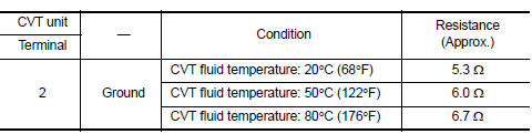
1.CHECK LINE PRESSURE SOLENOID VALVE
Check resistance between CVT unit connector terminal and ground.
 Is the inspection
result normal?
YES >> INSPECTION END
NO >> There is a malfunction of line pressure solenoid valve. Replace transaxle assembly. Refer to TM- 283, "Removal and Installation".
 P0744 Torque converter
DTC Logic
DTC DETECTION LOGIC
DTC
CONSULT screen terms
(Trouble diagnosis content)
DTC detection condition
Possible causes
P0744
TORQUE CONVERTER
(Torque converter ...
 P0846 Transmission fluid pressure SEN/SW B
DTC Logic
DTC DETECTION LOGIC
DTC
CONSULT screen terms
(Trouble diagnosis content)
DTC detection condition
Possible causes
P0846
TRANSMISSION FLUID
PRESSURE SEN/SW ...
Other materials:
System
Interior room lamp control system
INTERIOR ROOM LAMP CONTROL SYSTEM : System Diagram
WITH INTELLIGENT KEY
WITHOUT INTELLIGENT KEY
INTERIOR ROOM LAMP CONTROL SYSTEM : System Description
OUTLINE
Interior room lamp* is controlled by the interior room lamp timer
control function of t ...
P0447 EVAP Canister vent control valve
DTC Logic
DTC DETECTION LOGIC
DTC No.
CONSULT screen terms
(Trouble diagnosis content)
DTC detecting condition
Possible cause
P0447
VENT CONTROL VALVE
(Evaporative emission system vent
control circuit open)
An improper voltage signal is sent to
ECM throug ...
FM/AM/SAT radio with compact disc (CD) player (Type A) (if so equipped)
For all operation precautions, see “Audio operation
precautions” in this section.
Audio main operation
VOL (volume) knob / PWR (power) button:
Place the ignition switch in the ACC or ON
position and press the VOL (volume) knob /PWR
(power) button while the system is off to call up
the mod ...
