Nissan Sentra Service Manual: P0327, P0328 KS
DTC Logic
DTC DETECTION LOGIC
| DTC No. | CONSULT screen terms (Trouble diagnosis content) | DTC detecting condition | Possible cause |
| P0327 | KNOCK SEN/CIRC-B1 (Knock sensor 1 circuit low bank 1) | An excessively low voltage from the knock sensor is sent to ECM. |
|
| P0328 | KNOCK SEN/CIRC-B1 (Knock sensor 1 circuit high bank 1) | An excessively high voltage from the knock sensor is sent to ECM. |
DTC CONFIRMATION PROCEDURE
1.PRECONDITIONING
If DTC Confirmation Procedure has been previously conducted, always perform the following procedure before conducting the next test.
- Turn ignition switch OFF and wait at least 10 seconds.
- Turn ignition switch ON.
- Turn ignition switch OFF and wait at least 10 seconds.
TESTING CONDITION:
Before performing the following procedure, confirm that battery voltage is more than 10 V at idle.
>> GO TO 2.
2.PERFORM DTC CONFIRMATION PROCEDURE
- Start engine and run it for at least 5 seconds at idle speed.
- Check 1st trip DTC.
Is 1st trip DTC detected? YES >> Proceed to EC-275, "Diagnosis Procedure".
NO >> INSPECTION END
Diagnosis Procedure
1.CHECK KNOCK SENSOR GROUND CIRCUIT
- Turn ignition switch OFF.
- Disconnect knock sensor harness connector.
- Disconnect ECM harness connector.
- Check the continuity between knock sensor harness connector and ECM harness connector.
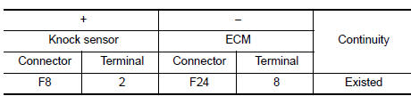
- Also check harness for short to power.
Is the inspection result normal? YES >> GO TO 2.
NO >> Repair or replace error-detected parts.
2.CHECK KNOCK SENSOR INPUT SIGNAL CIRCUIT
- Check the continuity between knock sensor harness connector and ECM harness connector.
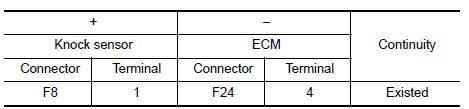
- Also check harness for short to ground and to power.
Is the inspection result normal? YES >> GO TO 3.
NO >> Repair open circuit or short to ground or short to power in harness or connectors.
3.CHECK KNOCK SENSOR
Check knock sensor. Refer to EC-276, "Component Inspection (KS)".
Is the inspection result normal? YES >> Check intermittent incident. Refer to GI-39, "Intermittent Incident".
NO >> Replace knock sensor. Refer to EM-94, "Exploded View".
Component Inspection (KS)
1.CHECK KNOCK SENSOR
- Turn ignition switch OFF.
- Disconnect knock sensor harness connector.
- Check resistance between knock sensor terminals as per the following.
NOTE:
It is necessary to use an ohmmeter which can measure more than 10 MΩ.
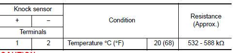
CAUTION:
Do not use any knock sensors that have been dropped or physically damaged. Use only new ones.
Is the inspection result normal? YES >> INSPECTION END
NO >> Replace knock sensor. Refer to EM-94, "Exploded View".
 P0300, P0301, P0302, P0303, P0304 Misfire
DTC Logic
DTC DETECTION LOGIC
When a misfire occurs, engine speed will fluctuate. If the engine speed
fluctuates enough to cause the crankshaft
position (CKP) sensor (POS) signal to vary, ECM can ...
 P0335 CKP Sensor (POS)
DTC Logic
DTC DETECTION LOGIC
NOTE:
If DTC P0340 is displayed with DTC P0643, first perform the trouble
diagnosis for DTC P0643. Refer to EC-
353, "DTC Logic".
DTC No.
CONSU ...
Other materials:
Excessive abs function operation
frequency
Diagnosis Procedure
1.CHECK START
Check front and rear brake force distribution using a brake
tester.
Is the inspection result normal?
YES >> GO TO 2
NO >> Check brake system.
2.CHECK FRONT AND REAR AXLE
Make sure that there is no excessive play in the front and rear
axles. ...
Electric ignition system
ELECTRIC IGNITION SYSTEM : System Description
SYSTEM DIAGRAM
*1: CVT models
*2: M/T models
Input/output signal chart
Sensor
Input Signal to ECM
ECM function
Actuator
Crankshaft position sensor (POS)
Engine speed*3
Piston position
Ignition ...
General Precaution
WARNING:
When replacing fuel line parts, be sure to observe the following.
Put a “CAUTION: FLAMMABLE” sign in the work area.
Be sure to work in a well ventilated area and have a CO2 fire
extinguisher.
Do not smoke while working on the fuel system. Keep open flames
and sparks ...
