Nissan Sentra Service Manual: P014C, P014D, P015A, P015B A/F Sensor 1
DTC Logic
DTC DETECTION LOGIC
To judge the malfunction of A/F sensor 1, this diagnosis measures response time of the A/F signal computed by ECM from the A/F sensor 1 signal. The time is compensated by engine operating (speed and load), fuel feedback control constant, and the A/F sensor 1 temperature index. Judgment is based on whether the compensated time (the A/F signal cycling time index) is inordinately long or not.
| DTC No. | CONSULT screen terms (Trouble diagnosis content) | DTC detecting condition | Possible cause |
| P014C | A/F SENSOR1 (B1) (O2 sensor slow response - rich to lean bank 1 sensor 1) | The response time of a A/F sensor 1 signal delays more than the specified time computed by ECM. |
|
| P014D | A/F SENSOR1 (B1) (O2 sensor slow response - lean to rich bank 1 sensor 1) |
DTC CONFIRMATION PROCEDURE
1.PRECONDITIONING
If DTC Confirmation Procedure has been previously conducted, always perform the following procedure before conducting the next test.
- Turn ignition switch OFF and wait at least 10 seconds.
- Turn ignition switch ON.
- Turn ignition switch OFF and wait at least 10 seconds.
TESTING CONDITION:
Before performing the following procedure, confirm that battery voltage is more than 11 V at idle.
Do you have CONSULT? YES >> GO TO 2.
NO >> GO TO 6.
2.PERFORM DTC CONFIRMATION PROCEDURE-1
 With CONSULT
- Start engine and warm it up to normal operating temperature.
- Turn ignition switch OFF and wait at least 10 seconds
- Turn ignition switch ON.
- Turn ignition switch OFF and wait at least 10 seconds
- Restart engine and keep the engine speed between 3,500 and 4,000 rpm for at least 1 minute under no load.
- Let engine idle for 1 minute.
- Increase the engine speed up to about 3,600 rpm and keep it for 10 seconds.
- Fully release accelerator pedal and then let engine idle for about 1 minute.
- On CONSULT screen, select “ENGINE” >> “DATA MONITOR” >> “A/F SEN1 DIAG3 (B1)”.
- Check that the data monitor indicates “PRSNT”.
NOTE:
If “PRSNT” changed to “ABSNT”, refer to EC-211, "Component Function Check".
Is“PRSNT” displayed on CONSULT screen? YES >> GO TO 4
NO >> GO TO 3.
3.PERFORM DTC CONFIRMATION PROCEDURE-2
 With CONSULT
Perform DTC confirmation procedure-1 again.
Is “PRSNT” displayed on CONSULT screen? YES >> GO TO 4.
NO >> Proceed to EC-211, "Component Function Check".
4.PERFORM DTC CONFIRMATION PROCEDURE-3
 With CONSULT
- Wait for about 20 seconds at idle.
- On CONSULT screen, select “ENGINE” >> “DATA MONITOR” >> “A/F SEN1 DIAG2 (B1)”.
- Check that the data monitor indicates “CMPLT”.
NOTE:
If “CMPLT” changed to “INCMP”, refer to EC-211, "Component Function Check".
Is “CMPLT” displayed on CONSULT screen? YES >> GO TO 5.
NO >> Refer to EC-211, "Component Function Check".
5.PERFORM SELF-DIAGNOSIS
 With CONSULT
Check the “SELF-DIAG RESULT”.
Is any DTC detected? YES >> Proceed to EC-240, "Diagnosis Procedure".
NO >> INSPECTION END
6.CHECK AIR-FUEL RATIO SELF-LEARNING VALUE
 With GST
- Start engine and warm it up to normal operating temperature.
- Select Service $01 with GST
- Calculate the total value of “Short term fuel trim” and “Long term fuel trim” indications.
Is the total percentage within В±15%? YES >> GO TO 8.
NO >> GO TO 7.
7.DETECT MALFUNCTIONING PART
Check the following.
- Intake air leaks
- Exhaust gas leaks
- Incorrect fuel pressure
- Lack of fuel
- Fuel injector
- Incorrect PCV hose connection
- PCV valve
- Mass air flow sensor
>> Repair or replace malfunctioning part.
8.PERFORM DTC CONFIRMATION PROCEDURE
- Turn ignition switch OFF and wait at least 10 seconds.
- Turn ignition switch ON.
- Turn ignition switch OFF and wait at least 10 seconds.
- Start engine and keep the engine speed between 3,500 and 4,000 rpm for at least 1 minute under no load.
- Let engine idle for 1 minute.
- Increase the engine speed up to about 3,600 rpm and keep it for 10 seconds.
- Fully release accelerator pedal and then let engine idle for about 1 minute.
- Check 1st trip DTC.
Is 1st trip DTC detected? YES >> Proceed to EC-240, "Diagnosis Procedure".
NO >> INSPECTION END
Diagnosis Procedure
1.RETIGHTEN A/F SENSOR 1
Loosen and retighten the A/F sensor 1. Refer to EM-30, "Exploded View".
>> GO TO 2.
2.CHECK EXHAUST GAS LEAK
- Start engine and run it at idle.
- Listen for an exhaust gas leak before three way catalyst 1.
Is exhaust gas leak detected? YES >> Repair or replace error-detected parts.
NO >> GO TO 3.
3.CHECK FOR INTAKE AIR LEAK
Listen for an intake air leak after the mass air flow sensor.
Is intake air leak detected? YES >> Repair or replace error-detected parts.
NO >> GO TO 4.
4.CLEAR THE MIXTURE RATIO SELF-LEARNING VALUE
- Clear the mixture ratio self-learning value. Refer to EC-142, "Work Procedure".
- Run engine for at least 10 minutes at idle speed.
Is the 1st trip DTC P0171 or P0172 detected? Is it difficult to start engine? YES >> • Perform trouble diagnosis for DTC P0171. Refer to EC-246, "DTC Logic".
• Perform trouble diagnosis for DTC P0172. Refer to EC-250, "DTC Logic".
NO >> GO TO 5.
5.CHECK AIR FUEL RATIO (A/F) SENSOR 1 POWER SUPPLY
- Turn ignition switch OFF.
- Disconnect A/F sensor 1 harness connector
- Turn ignition switch ON.
- Check the voltage between A/F sensor 1 harness connector and ground.
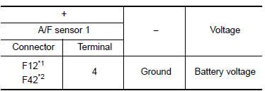
*1: Except California
*2: For California
Is the inspection result normal?
YES >> GO TO 6.
NO >> GO TO 11.
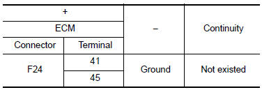
6.CHECK A/F SENSOR 1 INPUT SIGNAL CIRCUIT
- Turn ignition switch OFF.
- Disconnect ECM harness connector.
- Check the continuity between A/F sensor 1 harness connector and ECM harness connector.
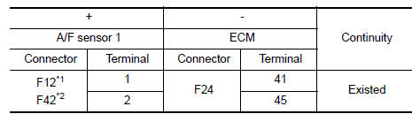
*1: Except California
*2: For California
- Check the continuity between A/F sensor 1 harness connector and ground or ECM harness connector and ground.
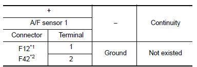
*1: Except California
*2: For California
- Also check harness for short to power.
Is the inspection result normal? YES >> GO TO 7.
NO >> Repair or replace error-detected parts.
7.CHECK AIR FUEL RATIO (A/F) SENSOR 1 HEATER
Check the air fuel ratio (A/F) sensor 1 heater. Refer to EC-242, "Component Inspection (A/F Sensor 1 Heater)".
Is the inspection result normal? YES >> GO TO 8.
NO >> Replace air fuel ratio (A/F) sensor 1. Refer to EM-30, "Exploded View".
8.CHECK MASS AIR FLOW SENSOR
Check the mass air flow sensor. Refer to EC-242, "Component Inspection (MAF Sensor)".
Is the inspection result normal? YES >> GO TO 9.
NO >> Replace mass air flow sensor. Refer to EM-25, "Exploded View".
9.CHECK PCV VALVE
Check the PCV valve. Refer to EC-484, "Inspection".
Is the inspection result normal? YES >> GO TO 10.
NO >> Repair or replace PCV valve. Refer to EC-15, "ENGINE CONTROL SYSTEM : Component Parts Location".
10.CHECK INTERMITTENT INCIDENT
Check intermittent incident. Refer to GI-39, "Intermittent Incident".
Is the inspection result normal? YES >> Replace air fuel ratio (A/F) sensor 1. Refer to EM-30, "Exploded View".
NO >> Repair or replace error-detected parts.
11.CHECK AIR FUEL RATIO (A/F) SENSOR 1 POWER SUPPLY CIRCUIT
- Turn ignition switch OFF.
- Disconnect IPDM E/R harness connector.
- Check the continuity between A/F sensor 1 harness connector and IPDM E/R harness connector
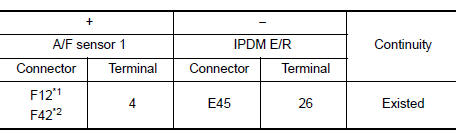
*1: Except California
*2: For California
- Also check harness for short to ground.
Is the inspection result normal? YES >> Perform the trouble diagnosis for power supply circuit.
NO >> Repair or replace error-detected parts.
Component Inspection (A/F Sensor 1 Heater)
1.CHECK AIR FUEL RATIO (A/F) SENSOR 1
- Turn ignition switch OFF.
- Disconnect A/F sensor 1 harness connector.
- Check resistance between A/F sensor 1 terminals as per the following.
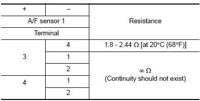
Is the inspection result normal? YES >> INSPECTION END
NO >> Replace air fuel ratio (A/F) sensor 1. Refer to EM-30, "Exploded View".
Component Inspection (MAF Sensor)
1.CHECK MASS AIR FLOW SENSOR-1
 With CONSULT
- Turn ignition switch OFF.
- Reconnect all harness connectors disconnected.
- Start engine and warm it up to normal operating temperature
- Connect CONSULT and select “DATA MONITOR” mode of “ENGINE”.
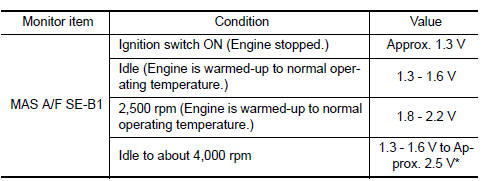
- Select “MAS A/F SE-B1” and check indication.
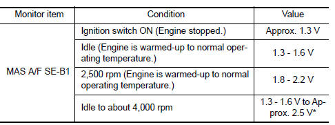
*: Check for linear voltage rise in response to engine being increased to about 4,000 rpm.
 Without CONSULT
- Turn ignition switch OFF.
- Reconnect all harness connectors disconnected.
- Start engine and warm it up to normal operating temperature.
- Check the voltage between ECM harness connector and ground.
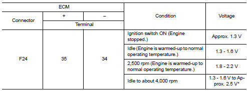
*: Check for linear voltage rise in response to engine being increased to about 4,000 rpm.
Is the inspection result normal? YES >> INSPECTION END
NO >> GO TO 2.
2.CHECK FOR THE CAUSE OF UNEVEN AIR FLOW THROUGH MASS AIR FLOW SENSOR
- Turn ignition switch OFF.
- Check for the cause of uneven air flow through mass air flow sensor. Refer to the following.
- Crushed air ducts
- Malfunctioning seal of air cleaner element
- Uneven dirt of air cleaner element
- Intake valve deposits
- Improper specification of intake air system parts
Is the inspection result normal? YES >> GO TO 4.
NO >> GO TO 3.
3.CHECK MASS AIR FLOW SENSOR-2
 With CONSULT
- Repair or replace malfunctioning part.
- Start engine and warm it up to normal operating temperature.
- Connect CONSULT and select “DATA MONITOR” mode of “ENGINE”.
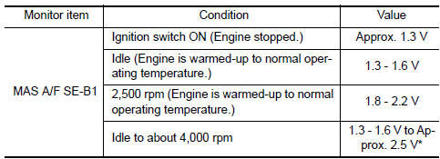
- Select “MAS A/F SE-B1” and check indication.
*: Check for linear voltage rise in response to engine being increased to about 4,000 rpm.
 Without CONSULT
- Repair or replace malfunctioning part.
- Start engine and warm it up to normal operating temperature.
- Check the voltage between ECM harness connector and ground.
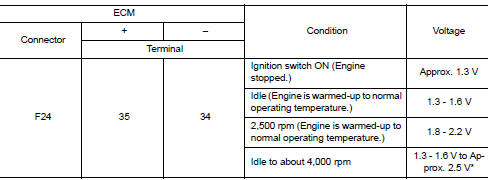
*: Check for linear voltage rise in response to engine being increased to about 4,000 rpm.
Is the inspection result normal? YES >> INSPECTION END
NO >> GO TO 4.
4.CHECK MASS AIR FLOW SENSOR-3
 With CONSULT
- Turn ignition switch OFF
- Disconnect mass air flow sensor harness connector and reconnect it again.
- Start engine and warm it up to normal operating temperature.
- Connect CONSULT and select “DATA MONITOR” mode of “ENGINE”.
- Select “MAS A/F SE-B1” and check indication.
*: Check for linear voltage rise in response to engine being increased to about 4,000 rpm.
 Without CONSULT
- Turn ignition switch OFF.
- Disconnect mass air flow sensor harness connector and reconnect it again.
- Start engine and warm it up to normal operating temperature.
- Check the voltage between ECM harness connector and ground.

*: Check for linear voltage rise in response to engine being increased to about 4,000 rpm.
Is the inspection result normal? YES >> INSPECTION END
NO >> Clean or replace mass air flow sensor. Refer to EM-25, "Exploded View".
 P0139 HO2S2
DTC Logic
DTC DETECTION LOGIC
The heated oxygen sensor 2 has a much longer switching time
between rich and lean than the air fuel ratio (A/F) sensor 1. The oxygen
storage capacity of the three way ...
 P0171 Fuel injection system function
DTC Logic
DTC DETECTION LOGIC
With the Air/Fuel Mixture Ratio Self-Learning Control, the actual mixture
ratio can be brought closely to the
theoretical mixture ratio based on the mixture ratio fe ...
Other materials:
Moonroof motor assembly
Exploded view
Headlining
Sun visor
Moonroof motor assembly
Front
Removal and installation
REMOVAL
Close the glass lid.
Remove the map lamp. Refer to INL-52, "Removal and Installation".
Remove the moonroof motor bolts (A).
Front
Disconnect the harness connec ...
Tire Pressure Monitoring System (TPMS)
This vehicle is equipped with the Tire Pressure
Monitoring System (TPMS). It monitors tire pressure
of all tires except the spare. When the low
tire pressure warning light is lit, and the CHECK
TIRE PRES warning message is displayed in the
odometer, one or more of your tires is significantly
u ...
Washer motor circuit
Diagnosis Procedure
Regarding Wiring Diagram information, refer to WW-24, "Wiring Diagram - With
Intelligent Key" or WW-29,
"Wiring Diagram - Without Intelligent Key".
1. Check front washer motor fuse
Turn the ignition switch OFF.
Check that the following fuse is not b ...
