Nissan Sentra Service Manual: P0171 Fuel injection system function
DTC Logic
DTC DETECTION LOGIC
With the Air/Fuel Mixture Ratio Self-Learning Control, the actual mixture ratio can be brought closely to the theoretical mixture ratio based on the mixture ratio feedback signal from the A/F sensors 1. The ECM calculates the necessary compensation to correct the offset between the actual and the theoretical ratios.
In case the amount of the compensation value is extremely large (The actual mixture ratio is too lean.), the ECM judges the condition as the fuel injection system malfunction and lights up the MIL (2 trip detection logic).
| Sensor | Input signal to ECM | ECM function | Actuator |
| A/F sensor 1 | Density of oxygen in exhaust gas (Mixture ratio feedback signal) | Fuel injection control | Fuel injector |
| DTC No. | CONSULT screen terms (Trouble diagnosis content) | DTC detecting condition | Possible cause |
| P0171 | FUEL SYS-LEAN-B1 (System too lean bank 1) |
|
|
DTC CONFIRMATION PROCEDURE
1.PRECONDITIONING
If DTC Confirmation Procedure has been previously conducted, always perform the following procedure before conducting the next test.
- Turn ignition switch OFF and wait at least 10 seconds.
- Turn ignition switch ON.
- Turn ignition switch OFF and wait at least 10 seconds.
>> GO TO 2.
2.PERFORM DTC CONFIRMATION PROCEDURE-1
- Clear the mixture ratio self-learning value. Refer to EC-142, "Work Procedure".
- Start engine
Is it difficult to start engine? YES >> GO TO 3.
NO >> GO TO 4.
3.RESTART ENGINE
If it is difficult to start engine, the fuel injection system has a malfunction, too.
Crank engine while depressing accelerator pedal.
NOTE:
When depressing accelerator pedal three-fourths (3/4) or more, the control system does not start the engine. Do not depress accelerator pedal too much.
Does engine start? YES >> Proceed to EC-247, "Diagnosis Procedure".
NO >> Check exhaust and intake air leak visually.
4.PERFORM DTC CONFIRMATION PROCEDURE-2
- Start engine and let it idle for at least 5 minutes.
- Check 1st trip DTC.
Is 1st trip DTC detected? YES >> Proceed to EC-247, "Diagnosis Procedure".
NO >> GO TO 5.
5.PERFORM DTC CONFIRMATION PROCEDURE-3
- Turn ignition switch OFF and wait at least 10 seconds.
- Start engine.
- Maintain the following conditions for at least 10 consecutive minutes.
Hold the accelerator pedal as steady as possible.

CAUTION:
Always drive vehicle at a safe speed.
- Check 1st trip DTC.
Is 1st trip DTC detected? YES >> Proceed to EC-247, "Diagnosis Procedure".
NO >> INSPECTION END
Diagnosis Procedure
1.CHECK EXHAUST GAS LEAK
- Start engine and run it at idle.
- Listen for an exhaust gas leak before three way catalyst (manifold).
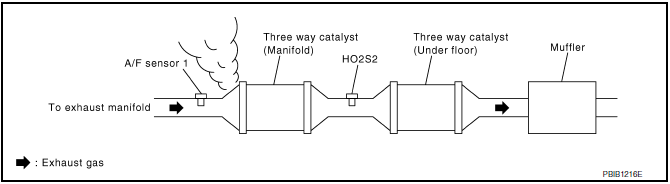
Is exhaust gas leak detected? YES >> Repair or replace error-detected parts.
NO >> GO TO 2.
2.CHECK FOR INTAKE AIR LEAK
- Listen for an intake air leak after the mass air flow sensor.
- Check PCV hose connection.
Intake air leak detected? YES >> Repair or replace error-detected parts.
NO >> GO TO 3.
3.CHECK A/F SENSOR 1 INPUT SIGNAL CIRCUIT
- Turn ignition switch OFF.
- Disconnect corresponding A/F sensor 1 harness connector.
- Disconnect ECM harness connector
- Check the continuity between A/F sensor 1 harness connector and ECM harness connector.
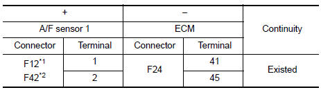
*1: Except California
*2: For California
- Check the continuity between A/F sensor 1 harness connector and ground, or ECM harness connector and ground
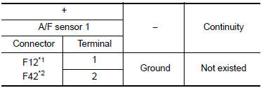
*1: Except California
*2: For California
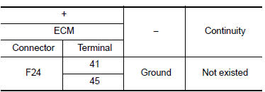
- Also check harness for short to power.
Is the inspection result normal? YES >> GO TO 4.
NO >> Repair or replace error-detected parts.
4.CHECK FUEL PRESSURE
Check fuel pressure. Refer to EC-143, "Work Procedure".
Is the inspection result normal? YES >> GO TO 6.
NO >> GO TO 5.
5. DETECT MALFUNCTIONING PART
Check fuel hoses and fuel tubes for clogging. Refer to EM-40, "Exploded View".
Is the inspection result normal? YES >> Replace “fuel filter and fuel pump assembly”. Refer to FL-6, "Exploded View".
NO >> Repair or replace error-detected parts.
6.CHECK MASS AIR FLOW SENSOR
 With CONSULT
- Install all removed parts.
- Check “MASS AIR FLOW” in “DATA MONITOR” mode of “ENGINE” using CONSULT.
- For specification, refer to EC-486, "Mass Air Flow Sensor".
 With GST
- Install all removed parts.
- Check mass air flow sensor signal in Service $01 with GST.
- For specification, refer to EC-486, "Mass Air Flow Sensor".
Is the measurement value within the specification? YES >> GO TO 7.
NO >> Check connectors for rusted terminals or loose connections in the mass air flow sensor circuit or grounds. Refer to EC-186, "DTC Logic".
7.CHECK FUNCTION OF FUEL INJECTOR
 With CONSULT
- Start engine.
- Perform “POWER BALANCE” in “ACTIVE TEST” mode of “ENGINE” using CONSULT.
- Make sure that each circuit produces a momentary engine speed drop.
 Without CONSULT
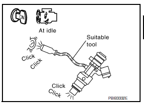
- Let engine idle.
- Listen to each fuel injector operating sound.
Clicking noise should be heard.
Is the inspection result normal? YES >> GO TO 8.
NO >> Perform trouble diagnosis for “FUEL INJECTOR”. Refer to EC-450, "Component Function Check".
8.CHECK FUEL INJECTOR
- Turn ignition switch OFF.
- Confirm that the engine is cooled down and there are no fire hazards near the vehicle.
- Disconnect all fuel injector harness connectors.
- Remove fuel tube assembly. Refer to EM-40, "Removal and Installation".
Keep fuel hose and all fuel injectors connected to fuel tube.
- Disconnect all ignition coil harness connectors.
- Prepare pans or saucers under each fuel injector.
- Crank engine for about 3 seconds.
Fuel should be sprayed evenly for each fuel injector.
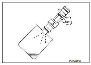
Is the inspection result normal?
YES >> Check intermittent incident. Refer to GI-39, "Intermittent Incident".
NO >> Replace fuel injectors from which fuel does not spray out. Always replace O-ring with new ones. Refer to EM- 40, "Removal and Installation".
 P014C, P014D, P015A, P015B A/F Sensor 1
DTC Logic
DTC DETECTION LOGIC
To judge the malfunction of A/F sensor 1, this diagnosis measures response
time of the A/F signal computed
by ECM from the A/F sensor 1 signal. The time is compensat ...
 P0172 Fuel injection system function
DTC Logic
DTC DETECTION LOGIC
With the Air/Fuel Mixture Ratio Self-Learning Control, the actual mixture
ratio can be brought closely to the
theoretical mixture ratio based on the mixture ratio fe ...
Other materials:
Precaution for Supplemental Restraint System (SRS) "AIR BAG" and "SEAT BELT
PRE-TENSIONER"
The Supplemental Restraint System such as “AIR BAG” and “SEAT BELT PRE-TENSIONER”,
used along
with a front seat belt, helps to reduce the risk or severity of injury to the
driver and front passenger for certain
types of collision. Information necessary to service the system ...
Parking brake
WARNING
Be sure the parking brake is fully released
before driving. Failure to do so
can cause brake failure and lead to an
accident.
Do not release the parking brake from
outside the vehicle.
Do not use the shift lever in place of the
parking brake. When parki ...
System
Tire pressure monitoring system
TIRE PRESSURE MONITORING SYSTEM : System Diagram
TIRE PRESSURE MONITORING SYSTEM : System Description
The BCM has pressure judgment and trouble diagnosis functions. When the
BCM detects low inflation pressure
or another unusual symptom, the low tire pr ...
