Nissan Sentra Service Manual: L terminal circuit (short)
Description
The terminal “l” circuit controls the charge warning lamp. The charge warning lamp turns on when the ignition switch is set to on or start. When the generator is providing sufficient voltage with the engine running, the charge warning lamp turns off. If the charge warning lamp illuminates with the engine running, a malfunction is indicated.
Diagnosis Procedure
Regarding wiring diagram information, refer to chg-9, "wiring diagram".
1.Check “l” terminal circuit (short)
- Turn ignition switch off.
- Disconnect generator connector.
- Turn ignition switch on.
Does charge warning lamp illuminate? YES >> GO TO 2.
NO >> Refer to CHG-14, "Work Flow (With EXP-800 NI or GR8-1200 NI)" or CHG-17, "Work Flow (Without EXP-800 NI or GR8-1200 NI)".
2.Check harness continuity (short circuit)
- Turn ignition switch off.
- Disconnect the battery cable from the negative terminal.
- Disconnect combination meter connector.
- Check continuity between the combination meter harness connector and ground.
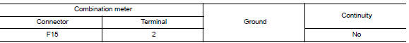
Is the inspection result normal? Yes >> replace the combination meter. Refer to mwi-77, "removal and installation".
No >> repair or replace the harness or connectors.
 L terminal circuit (open)
Description
The “L” terminal circuit controls the charge warning lamp. The charge warning
lamp turns ON when the ignition
switch is set to ON or START. When the generator is providing su ...
 S terminal circuit
Description
The output voltage of the generator is controlled by the IC regulator at
terminal “S” detecting the input voltage
from battery.
The “S” terminal circuit detects ...
Other materials:
Precautions in repairing high strength steel
High strength steel (HSS)
High strength steel is used for body panels in order to reduce vehicle
weight.
Accordingly, precautions in repairing automotive bodies made of high strength
steel are described below:
Tensile strength
Nissan/Infiniti designation
Major applicable parts
...
Diagnosis and repair work flow
Work Flow
NOTE:
The Signal Tech II Tool (J-50190) can be used to perform the following
functions. Refer to the Signal Tech II
User Guide for additional information.
Activate and display TPMS transmitter IDs
Display tire pressure reported by the TPMS transmitter
Read TPMS DTCs
Register ...
NISSAN Intelligent Key® (if so equipped)
Replace the battery in the Intelligent Key as follows:
Remove the mechanical key from the Intelligent
Key.
Insert a small screwdriver A into the slit B
of the corner and twist it to separate the
upper part from the lower part. Use a cloth to
protect the casing.
Replace the battery wi ...
