Nissan Sentra Service Manual: L terminal circuit (open)
Description
The “L” terminal circuit controls the charge warning lamp. The charge warning lamp turns ON when the ignition switch is set to ON or START. When the generator is providing sufficient voltage with the engine running, the charge warning lamp turns OFF. If the charge warning lamp illuminates with the engine running, a malfunction is indicated.
Diagnosis procedure
Regarding Wiring Diagram information. Refer to CHG-9, "Wiring Diagram".Ð Ñš
1.Check “l” terminal connection
- Turn ignition switch off.
- Check if “l” terminal is clean and tight.
Is the inspection result normal? Yes >> go to 2.
No >> repair “l” terminal connection. Confirm repair by performing complete charging system test using exp-800 ni or gr8-1200 ni (if available). Refer to applicable instruction manual for proper testing procedures.
2.Check “l” terminal circuit (open)
- Disconnect the generator connector.
- Apply ground to generator harness connector terminal.
- Check condition of the charge warning lamp with the ignition switch in the on position.
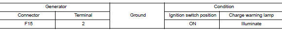
Does it illuminate? YES >> “L” terminal circuit is normal. Refer to CHG-14, "Work Flow (With EXP-800 NI or GR8-1200 NI)" or CHG-17, "Work Flow (Without EXP-800 NI or GR8-1200 NI)".
NO >> GO TO 3.
3.Check harness continuity (open circuit)
- Disconnect the battery cable from the negative terminal.
- Disconnect the combination meter connector.
- Check continuity between generator harness connector and combination meter harness connector.
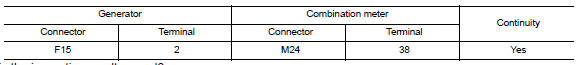
Is the inspection result normal? Yes >> go to 4.
No >> repair or replace the harness or connectors.
4.Check power supply circuit
- Connect the battery cable to the negative terminal.
- Check voltage between combination meter harness connector and ground.
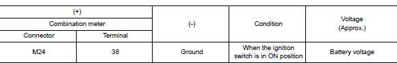
Is the inspection result normal? Yes >> replace the combination meter. Refer to mwi-77, "removal and installation".
No >> repair or replace the harness or connectors.
 B terminal circuit
Description
“B” terminal circuit supplies power to charge the battery and to operate the
vehicles electrical system.
Diagnosis procedure
Regarding wiring diagram information. Refer to c ...
 L terminal circuit (short)
Description
The terminal “l” circuit controls the charge warning lamp. The charge warning
lamp turns on when the ignition
switch is set to on or start. When the generator is providing s ...
Other materials:
Glove box lamp
Removal and installation
Warning:
Do not touch bulb while it is lit or right after being turned off.
Burning may result.
Caution:
Do not touch glass surface of the bulb with bare hands or allow oil or
grease to get on it to prevent
damage to bulb.
Removal
Remove the glove box assembly ...
ASCD Indicator
Component Function Check
1.CHECK ASCD INDICATOR FUNCTION
Check ASCD indicator under the following conditions.
ASCD INDICATOR
CONDITION
SPECIFICATION
CRUISE LAMP
Ignition switch: ON
MAIN switch: Pressed at the 1st time →
at the 2nd ti ...
Basic inspection
Diagnosis and repair workflow
Work flow
Overall sequence
Detailed flow
1.Obtain information about symptom
Interview the customer to obtain as much information as possible about the
conditions and environment under
which the malfunction occurred.
>> GO TO 2.
2.Check symptom
...
