Nissan Sentra Service Manual: S terminal circuit
Description
The output voltage of the generator is controlled by the IC regulator at terminal “S” detecting the input voltage from battery.
The “S” terminal circuit detects the battery voltage to adjust the generator output voltage with the IC voltage regulator.
Diagnosis procedure
Regarding wiring diagram information. Refer to chg-9, "wiring diagram".
1.Check “s” terminal connection
- Turn ignition switch OFF.
- Check if “s” terminal is clean and tight.
Is the inspection result normal? Yes >> go to 2.
No >> repair “s” terminal connection. Confirm repair by performing complete charging system test using exp-800 ni or gr8-1200 ni (if available). Refer to the applicable instruction manual for proper testing procedures.
2.Check “s” terminal circuit
Check voltage between generator harness connector and ground.
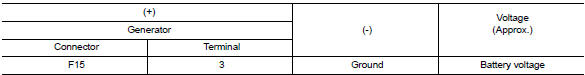
Is the inspection result normal? Yes >> refer to chg-14, "work flow (with exp-800 ni or gr8-1200 ni)" or chg-17, "work flow (without exp-800 ni or gr8-1200 ni)".
No >> check harness for open between generator and fuse.
 L terminal circuit (short)
Description
The terminal “l” circuit controls the charge warning lamp. The charge warning
lamp turns on when the ignition
switch is set to on or start. When the generator is providing s ...
 Symptom diagnosis
Charging system
Symptom table
...
Other materials:
Preparation
Special Service Tools
The actual shape of the tools may differ from those illustrated here.
Commercial Service Tools
Clip list
Descriptions for Clips
Replace any clips which are damaged during removal or installation.
...
Heater and air conditioner (automatic) (if so equipped)
Temperature control buttons (driver’s
side)
(front defroster) button
(rear window defroster)
button
Display screen
MODE (manual air flow control) button
Fresh air intake button
Air recirculation button
Temperature control buttons (passenger’s
side)
DUAL button
...
Precaution
Precaution for supplemental restraint system (srs) "air bag" and "seat
belt pre-tensioner"
The supplemental restraint system such as “air bag” and “seat belt pre-tensioner”,
used along
with a front seat belt, helps to reduce the risk or severity of injur ...
