Nissan Sentra Service Manual: Dlc branch line circuit
Diagnosis Procedure
1.Check connector
- Turn the ignition switch off.
- Disconnect the battery cable from the negative terminal
- Check the terminals and connectors of the data link connector for damage, bend and loose connection (connector side and harness side).
Is the inspection result normal? Yes >> go to 2.
No >> repair the terminal and connector.
2.Check harness for open circuit
Check the resistance between the data link connector terminals.
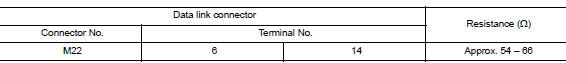
Is the measurement value within the specification? YES (Present error)>>Check CAN system type decision again.
YES (Past error)>>Error was detected in the data link connector branch line circuit.
NO >> Repair the data link connector branch line.
 A-bag branch line circuit
Diagnosis procedure
Warning:
Always observe the following items for preventing accidental
activation.
Before servicing, turn ignition switch off, disconnect battery
negative terminal, and w ...
 Eps branch line circuit
Diagnosis Procedure
1.Check connector
Turn the ignition switch off.
Disconnect the battery cable from the negative terminal.
Check the terminals and connectors of the eps control unit for dam ...
Other materials:
Three-point type seat belt with retractor
WARNING
Every person who drives or rides in this
vehicle should use a seat belt at all
times.
Do not ride in a moving vehicle when
the seatback is reclined. This can be
dangerous. The shoulder belt will not
be against your body. In an accident,
you could be thr ...
Evap canister
Exploded View
EVAP canister bracket
EVAP canister filter drain hose
EVAP canister filter
EVAP canister protector
EVAP hose
EVAP canister vent control valve
O-ring
EVAP canister
O-ring
EVAP canister control pressure sensor
Clip
Nut
Removal and Installation
EVAP ...
Power window and door lock/unlock switch RH
Removal and Installation
REMOVAL
Release the pawls using a suitable tool and lift the power window and
door lock/unlock switch RH and finisher
as an assembly and remove.
Disconnect the harness connector from the power window and door
lock/unlock switch RH.
Release the four pawls (tw ...
