Nissan Sentra Service Manual: Diagnosis and repair work flow
Work Flow
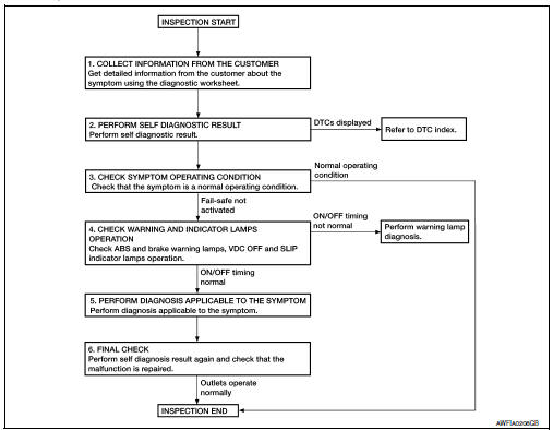
OVERALL SEQUENCE
DETAILED FLOW
1.COLLECT INFORMATION FROM THE CUSTOMER
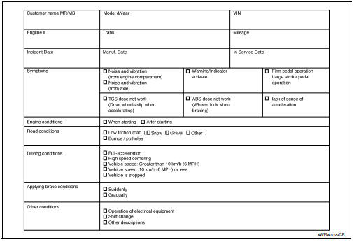
Get detailed information from the customer about the symptom (the condition and the environment when the incident/malfunction occurred) using the diagnostic worksheet. Refer to BRC-52, "Diagnostic Work Sheet".
>> GO TO 2.
2.PERFORM SELF DIAGNOSTIC RESULT
Perform self diagnostic result. Refer to BRC-31, "CONSULT Function (ABS)".
Are any DTCs displayed? YES >> Refer to BRC-43, "DTC Index".
NO >> GO TO 3.
3.CHECK SYMPTOM OPERATING CONDITION
Check that the symptom is a normal operating condition. Refer to BRC-105, "Description".
Is the symptom a normal operating condition? YES >> Inspection End.
NO >> GO TO 4.
4.CHECK WARNING AND INDICATOR LAMPS OPERATION
Check ABS and brake warning lamps, and VDC OFF and SLIP indicator lamps operation. Refer to MWI-8, "METER SYSTEM : System Description".
Is ON/OFF timing normal? YES >> GO TO 5.
NO >> Perform warning lamp diagnosis. Refer to BRC-94, "Component Function Check" (ABS warning lamp), BRC-95, "Component Function Check" (brake warning lamp), BRC-96, "Component Function Check" (VDC OFF indicator lamp) or BRC-97, "Component Function Check" (SLIP indicator lamp).
5.PERFORM DIAGNOSIS APPLICABLE TO THE SYMPTOM
Perform diagnosis applicable to the symptom. Refer to BRC-98, "Symptom Table".
>> GO TO 6.
6.FINAL CHECK
Perform self diagnostic result again, and check that the malfunction is repaired. After checking, erase the self diagnosis memory. Refer to BRC-31, "CONSULT Function (ABS)".
>> Inspection End
Diagnostic Work Sheet
Additional service when replacing abs actuator and electric unit (control unit)
Description
When replacing the ABS actuator and electric unit (control unit), perform steering angle sensor neutral position adjustment. Refer to BRC-54, "Work Procedure".
 Basic inspection
...
 Adjustment of steering angle sensor neutral position
Description
Refer to the table below to determine if adjustment of steering
angle sensor neutral position is required.
×: Required –: Not required
Work Procedure
ADJUSTMENT OF ST ...
Other materials:
Clutch master cylinder
Exploded View
Reservoir hose
Reservoir tank
Clutch master cylinder
Removal and Installation
REMOVAL
CAUTION:
Keep painted surface on the body or other parts free of clutch
fluid. If it spills, wipe up immediately
and wash the affected area with water.
Do not disassemble c ...
Intake manifold tuning system
INTAKE MANIFOLD TUNING SYSTEM : System
Description
SYSTEM DIAGRAM
SYSTEM DESCRIPTION
This system switches the length of intake air path according to the
low-to-medium speed range or high speed
range. Torque is increased in the low-to-medium speed range and the engine
output is improved ...
Operating tips
When the engine coolant temperature and
outside air temperature are low, the air flow
from the foot outlets may not operate for a
maximum of 150 seconds. However, this is
not a malfunction. After the coolant temperature
warms up, air flow from the foot outlets
will operate normally.
...
