Nissan Sentra Service Manual: Adjustment of steering angle sensor neutral position
Description
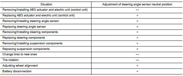
Refer to the table below to determine if adjustment of steering angle sensor neutral position is required.
×: Required –: Not required
Work Procedure
ADJUSTMENT OF STEERING ANGLE SENSOR NEUTRAL POSITION
CAUTION:
To adjust neutral position of steering angle sensor, make sure to use CONSULT.
(Adjustment cannot be done without CONSULT).
1.ALIGN THE VEHICLE STATUS
Stop vehicle with front wheels in straight-ahead position.
>> GO TO 2.
2.PERFORM THE NEUTRAL POSITION ADJUSTMENT FOR THE STEERING ANGLE SENSOR
-
On the CONSULT screen, touch “WORK SUPPORT” and “ST ANG SEN ADJUSTMENT” in order.
-
Touch “START”.
CAUTION:
Do not touch steering wheel while adjusting steering angle sensor.
-
After approximately 10 seconds, touch “END”.
NOTE:
After approximately 60 seconds, it ends automatically.
-
Turn ignition switch OFF, then turn it ON again.
CAUTION:
Be sure to perform above operation.
>> GO TO 3.
3.CHECK DATA MONITOR
-
Run vehicle with front wheels in straight-ahead position, then stop
-
Select “DATA MONITOR”. Then make sure “STR ANGLE SIG” is within 0±2.5°.
Is the steering angle within the specified range? YES >> GO TO 4.
NO >> Perform the neutral position adjustment for the steering angle sensor again, GO TO 1
4.ERASE THE SELF-DIAGNOSIS MEMORY
Erase the self-diagnosis memory of the ABS actuator and electric unit (control unit) and ECM.
-
ABS actuator and electric unit (control unit): Refer to BRC-31, "CONSULT Function (ABS)".
-
ECM: Refer to EC-66, "CONSULT Function".
Are the memories erased? YES >> Inspection End
NO >> Check the items indicated by the self-diagnosis.
 Diagnosis and repair work flow
Work Flow
OVERALL SEQUENCE
DETAILED FLOW
1.COLLECT INFORMATION FROM THE CUSTOMER
Get detailed information from the customer about the symptom
(the condition and the environment when the
in ...

Other materials:
System
SRS air bag system
SRS AIR BAG SYSTEM : System Diagram
SRS AIR BAG SYSTEM : System Description
The air bag deploys if the air bag diagnosis sensor unit is activated
while the ignition switch is in the ON or
START position.
The collision modes for which supplemental restraint systems ...
L terminal circuit (short)
Description
The terminal “l” circuit controls the charge warning lamp. The charge warning
lamp turns on when the ignition
switch is set to on or start. When the generator is providing sufficient voltage
with the engine running,
the charge warning lamp turns off. If the charge warni ...
Push starting
CAUTION
Do not push start this vehicle. The
three-way catalyst may be damaged.
Continuously Variable Transmission
(CVT) models and Manual Transmission
(MT) cannot be push-started or towstarted.
Attempting to do so may cause
transmission damage
For manual transmission (MT) models,
...
