Nissan Sentra Service Manual: P0132 A/F SENSOR 1
DTC Logic
DTC DETECTION LOGIC
To judge the malfunction, the diagnosis checks that the A/F signal computed by ECM from the A/F sensor 1 signal is not inordinately high.
| DTC No. | CONSULT screen terms (Trouble diagnosis content) | DTC detecting condition | Possible cause |
| P0132 | A/F SENSOR1 (B1) (O2 sensor circuit high voltage bank 1 sensor 1) | The A/F signal computed by ECM from the A/F sensor 1 signal is constantly approx. 5 V. |
|
DTC CONFIRMATION PROCEDURE
1.PRECONDITIONING
If DTC Confirmation Procedure has been previously conducted, always perform the following procedure before conducting the next test.
- Turn ignition switch OFF and wait at least 10 seconds.
- Turn ignition switch ON.
- Turn ignition switch OFF and wait at least 10 seconds.
TESTING CONDITION:
Before performing the following procedure, confirm that battery voltage is more than 10.5 V at idle.
>> GO TO 2.
2.CHECK A/F SENSOR FUNCTION
 With CONSULT
- Start engine and warm it up to normal operating temperature.
- Select “A/F SEN1 (B1)” in “DATA MONITOR” mode of “ENGINE” using CONSULT
- Check “A/F SEN1 (B1)” indication.
 With GST
Follow the procedure “With CONSULT” above.
Is the indication constantly approx. 5 V? YES >> Proceed to EC-218, "Diagnosis Procedure".
NO >> GO TO 3.
3.PERFORM DTC CONFIRMATION PROCEDURE
 With CONSULT
- Turn ignition switch OFF, wait at least 10 seconds and then restart engine.
- Drive and accelerate vehicle to more than 40 km/h (25 MPH) within 20 seconds after restarting engine.
CAUTION:
Always drive vehicle at a safe speed.
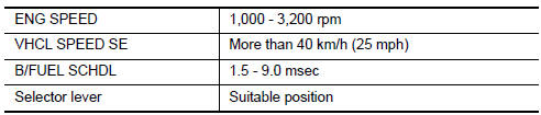
- Maintain the following conditions for about 20 consecutive seconds.
NOTE:
- Keep the accelerator pedal as steady as possible during the cruising.
- If this procedure is not completed within 1 minute after restarting engine at step 1, return to step 1.
- Check 1st trip DTC.
 With GST
Follow the procedure “With CONSULT” above.
Is 1st trip DTC is detected? YES >> Proceed to EC-218, "Diagnosis Procedure".
NO >> INSPECTION END
Diagnosis Procedure
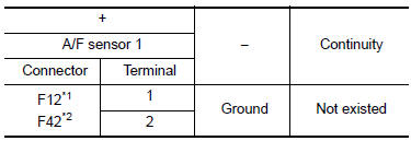
1.CHECK AIR FUEL RATIO (A/F) SENSOR 1 POWER SUPPLY
- Turn ignition switch OFF.
- Disconnect A/F sensor 1 harness connector.
- Turn ignition switch ON.
- Check the voltage between A/F sensor 1 harness connector and ground.
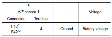
*1: Except California
*2: For California
Is the inspection result normal? YES >> GO TO 3.
NO >> GO TO 2.
2.CHECK AIR FUEL RATIO (A/F) SENSOR 1 POWER SUPPLY CIRCUIT
- Turn ignition switch OFF.
- Disconnect IPDM E/R harness connector.
- Check the continuity between A/F sensor 1 harness connector and IPDM E/R harness connector.
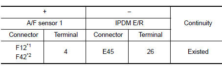
*1: Except California
*2: For California
- Also check harness for short to ground.
Is the inspection result normal? YES >> Perform the trouble diagnosis for power supply circuit.
NO >> Repair or replace error-detected parts.
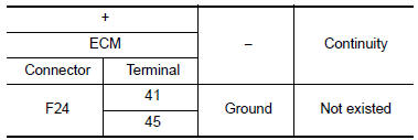
3.CHECK A/F SENSOR 1 INPUT SIGNAL CIRCUIT
- Turn ignition switch OFF.
- Disconnect ECM harness connector
- Check the continuity between A/F sensor 1 harness connector and ECM harness connector.
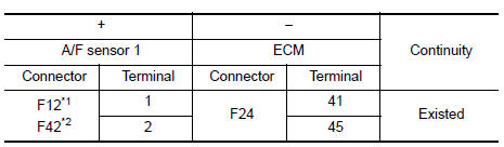
*1: Except California
*2: For California
- Check the continuity between A/F sensor 1 harness connector and ground, or ECM harness connector and ground.
*1: Except California
*2: For California
- Also check harness for short to power.
Is the inspection result normal? YES >> GO TO 4.
NO >> Repair or replace error-detected parts.
4.CHECK INTERMITTENT INCIDENT
Check intermittent incident. Refer to GI-39, "Intermittent Incident".
Is the inspection result normal? YES >> Replace air fuel ratio (A/F) sensor 1. Refer to EM-30, "Exploded View".
NO >> Repair or replace error-detected parts.
 P0131 A/F Sensor 1
DTC Logic
DTC DETECTION LOGIC
To judge the malfunction, the diagnosis checks that the A/F signal computed
by ECM from the A/F sensor 1
signal is not inordinately low.
DTC No.
CONSULT s ...
 P0137 HO2S2
DTC Logic
DTC DETECTION LOGIC
The heated oxygen sensor 2 has a much longer switching time
between rich and lean than the air fuel ratio (A/F) sensor 1. The oxygen
storage capacity of the three way ...
Other materials:
Component parts
Component Parts Location
BCM (view under instrument panel
on the left side of the vehicle)
Front power window motor LH (RH
similar) (view with front door finisher
removed)
Rear power window motor LH (RH
similar) (view with rear door finisher
removed)
Main power window and do ...
Heating and cooling unit assembly
Exploded view
With air conditioning
Defroster seal
Center ventilator seal
Upper distribution module
Side ventilator seal (LH)
Blower motor
Blower unit
Intake door motor
Power transistor
Power transistor wiring harness
Front floor duct (lh)
Vent and defroster linkage
Mo ...
Diagnosis system (ipdm e/r) (without intelligent key system)
Diagnosis Description
AUTO ACTIVE TEST
Description
In auto active test, the IPDM E/R sends a drive signal to the following
systems to check their operation.
Front wiper (LO, HI)
Parking lamp
License plate lamp
Tail lamp
Front fog lamp (if equipped)
Headlamp (LO, HI)
A/C compress ...
