Nissan Sentra Service Manual: Removal and installation
Av control unit
Exploded view
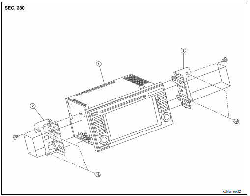
- AV control unit
- Av control unit bracket (lh)
- AV control unit bracket (RH)
Removal and installation
Removal
Caution:
- Remove battery terminal and av control unit after a lapse of 30 seconds or more after turning the ignition switch off.
- Before replacing av control unit, perform "read configuration" to
save current vehicle specification.
Refer to av-351, "configuration (av control unit) : configuration list".
- Disconnect the negative battery terminal. Refer to pg-50, "removal and installation (battery)".
- Remove cluster lid c lower. Refer to ip-20, "removal and installation - cluster lid c lower".
- Remove the AV control unit screws, then pull out the AV control unit.
- Disconnect the harness connectors from the av control unit and remove.
Installation
Installation is in the reverse order of removal.
Caution:
When replacing av control unit, perform "write configuration". Refer to av-351, "configuration (av control unit) : configuration list".
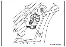
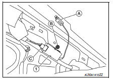
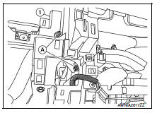
Front tweeter
Removal and installation
Removal
- Remove the front pillar finisher. Refer to int-24, "front pillar finisher : removal and installation".
- Disconnect the harness connector (b) from the front tweeter speaker.
- Remove the front tweeter speaker screw (A) from the front tweeter speaker (1) and remove.
Installation
Installation is in the reverse order of removal.
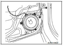
Front door speaker
Removal and Installation
Removal
- Remove the front door finisher. Refer to int-15, "removal and installation".
- Remove the front door speaker screws (b).
- Disconnect the harness connector (A) from the front door speaker (1) and remove.
Installation
Installation is in the reverse order of removal.
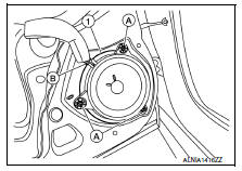
Rear door speaker
Removal and installation
Removal
- Remove the rear door finisher. Refer to int-19, "removal and installation".
- Remove the rear door speaker screws (A).
- Disconnect the harness connector (b) from the rear door speaker (1) and remove.
Installation
Installation is in the reverse order of removal.
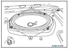
Rear woofer
Removal and Installation
Removal
- Remove the rear parcel shelf finisher. Refer to int-33, "removal and installation".
- Remove the rear woofer screws (a).
- Disconnect the harness connector from the rear woofer (1) and remove.
Installation
Installation is in the reverse order of removal.
Steering switch
Exploded View
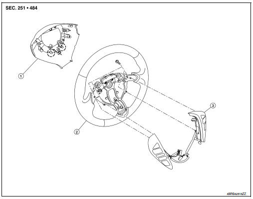
- Steering wheel rear finisher
- Steering wheel
- Steering switches
 Pawl
Pawl
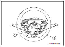
Removal and Installation
Removal
- Remove the steering wheel. Refer to st-10, "removal and installation".
- Release the pawls on the steering wheel rear finisher and remove.
- Remove the steering switches screws (a).
- Remove the steering switches (1) from steering wheel (2).
Installation
Installation is in the reverse order of removal.
Antenna feeder
Location of antenna
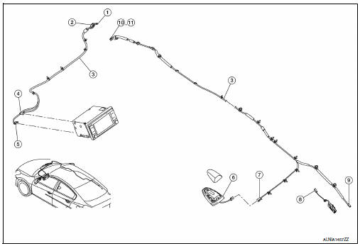
- M112
- M107
- Antenna feeder
- M143
- M145
- Satellite antenna
- M504
- M503
- M502
- M500
- M501
Window antenna repair
Element check
- Attach probe circuit tester (ohm setting) to antenna terminal on each side.
- When measuring continuity, wrap tin foil around the top of probe. Then, press the foil against the wire with your finger.
- If an element is broken, no continuity will exist.
- To locate a break, move probe along element. Tester indication will change abruptly when probe passes the broken point.
Repair equipment
- Conductive silver composition (dupont no. 4817 Or equivalent)
- Ruler 30 cm (11.8 In) long
- Drawing pen
- Heat gun
- Alcohol
- Cloth
Repairing procedure
- Wipe broken heat wire and its surrounding area clean with a cloth dampened in alcohol.
- Apply a small amount of conductive silver composition to tip of
drawing pen.
Shake silver composition container before use.
- Place ruler on glass along broken line. Deposit conductive silver composition on break with drawing pen. Slightly overlap existing heat wire on both sides [preferably 5 mm (0.20 In)] of the break.
- After repair has been completed, check repaired wire for continuity.
This check should be conducted 10 minutes after silver composition is deposited.
Do not touch repaired area while test is being conducted.
- Apply a constant stream of hot air directly to the repaired area
for approximately 20 minutes with a heat gun. A minimum distance
of 3 cm (1.2 In) should be kept between repaired area and
hot air outlet.
If a heat gun is not available, let the repaired area dry for 24 hours.
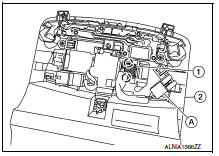
Antenna amp.
Removal and installation
Removal
- Remove the rear pillar finisher (RH). Refer to INT-29, "REAR PILLAR FINISHER : Removal and Installation".
- Disconnect the antenna amp. harness connector (A) from the rear window glass.
- Disconnect the harness connector (C) from the antenna amp.
(1).
- Remove the antenna amp. Screw (b) and the antenna amp. (1).
Installation
Installation is in the reverse order of removal.
USB connector and aux jack
Removal and installation
Removal
- Remove the center console rear finisher cover. Refer to tm-253, "exploded view".
- Release the pawls and remove the usb connector and aux jack
(1) From the center console rear finisher cover.
 Pawl
Pawl
 Front
Front
Installation
Installation is in the reverse order of removal.
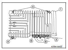
Bose speaker amp
Removal and installation
Removal
- Open the trunk lid.
- Remove the bose speaker amp. Screws (a).
- Disconnect the harness connectors (b) from the bose speaker amp. (1) And remove.
Installation
Installation is in the reverse order of removal.
Window antenna
Removal and installation
The window antenna is serviced as an assembly with the filament. Refer to DEF-47, "Inspection and Repair".
Revision: October
Satellite radio antenna
Removal and installation
Removal
- Lower the headlining at the rear. Refer to INT-38, "Exploded View".
- Remove the satellite radio antenna nut (A).
- Disconnect the harness connector (b) from the satellite radio antenna (1) and remove.
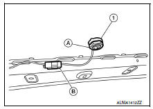
Installation
Installation is in the reverse order of removal.
GPS antenna
Removal and Installation
Removal
- Remove the combination meter. Refer to mwi-77, "removal and installation".
- Remove the AV control unit. Refer to AV-406, "Removal and Installation".
- Remove the screw (a) from the gps antenna (1).
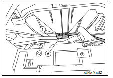
- Release the harness clips (A) from the instrument panel (1) and remove the GPS antenna.
Installation
Installation is in the reverse order of removal.
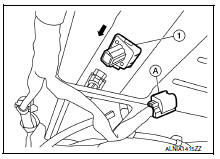
Microphone
Removal and installation
Removal
- Remove the front room/map lamp assembly. Refer to inl-52, "removal and installation".
- Disconnect the microphone connector (a) from the front room/ map lamp assembly (2).
- Release the microphone pawls, then remove the microphone (1).
 : Pawl
Installation
Installation is in the reverse order of removal.
Rear view camera
Removal and installation
Removal
- Remove trunk lid finisher. Refer to INT-45, "Removal and Installation".
- Disconnect the harness connector (a) from rear view camera (1).
- Remove the license lamp finisher. Refer to ext-44, "removal and installation".
- Push the rear view camera (1) in direction shown (
 ) and pull
out to remove.
Installation
Installation is in the reverse order of removal.
 Symptom diagnosis
Multi av system
Symptom table
Related to audio
Related to hands-free phone
Before performing diagnosis, confirm that the cellular phone being used
by the customer is compatible w ...

Other materials:
C1155 BR Fluid level low
DTC Logic
Dtc detection logic
Dtc
Display item
Malfunction detected condition
Possible cause
C1155
C1155 br fluid level low
Brake fluid level is low or communication line between
the abs actuator and electric unit (control unit) and brake
fluid level switch is ...
Ecm branch line circuit
Diagnosis procedure
1.Check connector
Turn the ignition switch OFF.
Disconnect the battery cable from the negative terminal.
Check the terminals and connectors of the ECM for damage, bend and loose
connection (unit side and
connector side).
Is the inspection result normal?
Yes > ...
Wiring diagram
Display audio with bose
Wiring diagram
...
