Nissan Sentra Service Manual: Can communication circuit
Diagnosis procedure
1.Connector inspection
- Turn the ignition switch off.
- Disconnect the battery cable from the negative terminal.
- Disconnect all the unit connectors on CAN communication system.
- Check terminals and connectors for damage, bend and loose connection.
Is the inspection result normal? YES >> GO TO 2.
NO >> Repair the terminal and connector.
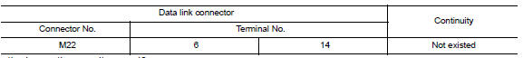
2.Check harness continuity (short circuit)
Check the continuity between the data link connector terminals.
Is the inspection result normal? Yes >> go to 3.
No >> check the harness and repair the root cause.
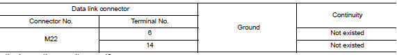
3.Check harness continuity (short circuit)
Check the continuity between the data link connector and the ground.
Is the inspection result normal? Yes >> go to 4.
No >> check the harness and repair the root cause.
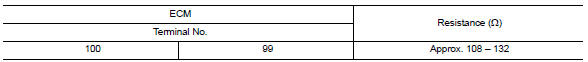
4.Check ecm and bcm termination circuit
- Remove the ecm and the bcm.
- Check the resistance between the ECM terminals.
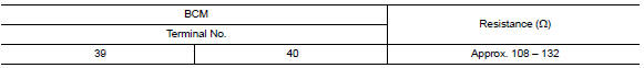
- Check the resistance between the bcm terminals.
Is the measurement value within the specification? YES >> GO TO 5.
NO >> Replace the ECM and/or the BCM.
5.Check symptom
Connect all the connectors. Check if the symptoms described in the “symptom (results from interview with customer)” are reproduced.
Inspection result
Reproduced>>GO TO 6.
Non-reproduced>>Start the diagnosis again. Follow the trouble diagnosis procedure when past error is detected.
6.Check unit reproduction
Perform the reproduction test as per the following procedure for each unit.
- Turn the ignition switch off.
- Disconnect the battery cable from the negative terminal.
- Disconnect one of the unit connectors of can communication system.
Note:
Ecm and bcm have a termination circuit. Check other units first.
- Connect the battery cable to the negative terminal. Check if the symptoms described in the “symptom (results from interview with customer)” are reproduced.
Note:
Although unit-related error symptoms occur, do not confuse them with other symptoms.
Inspection result
Reproduced>>connect the connector. Check other units as per the above procedure.
Non-reproduced>>replace the unit whose connector was disconnected.
 Bcm branch line circuit
Diagnosis Procedure
1.Check connector
Turn the ignition switch off.
Disconnect the battery cable from the negative terminal.
Check the terminals and connectors of the BCM for damage, bend and ...
 Can system (type 4)
Dtc/circuit diagnosis ...
Other materials:
Rear combination lamp
Exploded View
Rear combination lamp
Rear turn signal lamp bulb
Rear turn signal lamp socket
LED lamp harness connector
Rear combination lamp harness
connector
Back-up lamp bulb socket
Back-up lamp bulb
Disassembly and Assembly
DISASSEMBLY
WARNING:
Do not touch bulb whil ...
Parking brake control
Exploded View
Parking brake lever assembly
Adjusting nut
Parking brake switch
Front parking brake cable
Rear parking brake cable (LH)
Rear parking brake cable (RH)
Front
Removal and Installation
REMOVAL
Parking Brake Control
Remove rear wheels and t ...
Secondary speed sensor
Exploded View
Transaxle assembly
O-ring
Secondary speed sensor
Vehicle front
Always replace after every
disassembly.
: NВ·m (kg-m, in-lb)
: Genuine NISSAN CVT Fluid NS-3
Removal and Installation
REMOVAL
Disconnect the secondary speed sensor connector.
Remove the s ...
