Nissan Sentra Service Manual: Bcm branch line circuit
Diagnosis Procedure
1.Check connector
- Turn the ignition switch off.
- Disconnect the battery cable from the negative terminal.
- Check the terminals and connectors of the BCM for damage, bend and loose connection (unit side and connector side).
Is the inspection result normal? YES >> GO TO 2.
NO >> Repair the terminal and connector.
2.Check harness for open circuit
- Disconnect the connector of BCM.
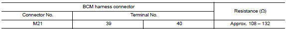
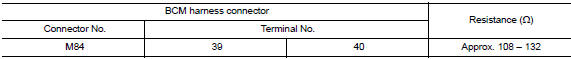
- Check the resistance between the BCM harness connector terminals.
- Without intelligent key system
- With Intelligent Key system
Is the measurement value within the specification? Yes >> go to 3.
No >> repair the bcm branch line.
3.Check power supply and ground circuit
Check the power supply and the ground circuit of the bcm. Refer to the following.
- With intelligent key system: refer to bcs-67, "diagnosis procedure".
- Without intelligent key system: refer to bcs-120, "diagnosis procedure".
Is the inspection result normal? Yes (present error)>>replace the bcm. Refer to the following.
- With intelligent key system: refer to bcs-73, "removal and installation".
- Without Intelligent Key system: Refer to BCS-126, "Removal and Installation".
Yes (past error)>>error was detected in the bcm branch line.
No >> repair the power supply and the ground circuit.
 AV branch line circuit
Diagnosis procedure
1.Check connector
Turn the ignition switch off
Disconnect the battery cable from the negative terminal.
Check the terminals and connectors of the av control unit for damag ...
 Can communication circuit
Diagnosis procedure
1.Connector inspection
Turn the ignition switch off.
Disconnect the battery cable from the negative terminal.
Disconnect all the unit connectors on CAN communication syste ...
Other materials:
ID registration cannot be completed
Diagnosis Procedure
NOTE:
The Signal Tech II Tool (J-50190) can be used to perform the following
functions. Refer to the Signal Tech II
User Guide for additional information.
Activate and display TPMS transmitter IDs
Display tire pressure reported by the TPMS transmitter
Read TPMS DTCs
...
Brake master cylinder
Inspection
Check for brake fluid leakage at the following areas:
Master cylinder mounting face
Reservoir tank mounting face
Brake tube and brake tube connections
Brake hose and brake hose connections
If any brake fluid leakage is found, repair as necessary.
On Board Inspection
LEAK ...
Rear door finisher
Exploded View
Rear door panel
Rear door finisher
Inside door handle escutcheon
Rear power window switch finisher
Grommet
Clip
Pawl
Front
Removal and Installation
CAUTION:
When removing, always use a suitable tool that is made of plastic
to prevent damage to the p ...
