Nissan Sentra Service Manual: Battery saver output/power supply circuit
Description
Provides the battery saver output/power supply. Also cuts the power supply when the interior lamp battery saver is activated.
Component function check
1.Check battery saver output/power supply function
 Consult
- Turn ignition switch on.
- Turn each interior lamp to the ON position.
- Interior room lamp
- Vanity mirror lamps
- Map lamp
- Trunk room lamp
- Select battery saver of bcm (battery saver) active test item.
- While operating the test item, check that each interior room lamp turns ON/OFF.
Off : interior room lamp off
On : interior room lamp on
Is the inspection result normal? Yes >> battery saver output/power supply circuit is normal.
No >> refer to inl-43, "diagnosis procedure".
Diagnosis procedure
Regarding wiring diagram information, refer to inl-17, "wiring diagram".
1.Check battery saver output/power supply output
 Consult
- Turn ignition switch on.
- Select battery saver of bcm (battery saver) active test item.
- While operating the test item, check voltage between BCM connector and ground.
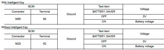
Is the inspection result normal? Yes >> go to 2.
No >> replace bcm after making sure battery saver output/power supply circuit is not shorted to voltage.
Refer to bcs-73, "removal and installation" (with intelligent key) or bcs-126, "removal and installation" (without intelligent key).
2.Check battery saver output/power supply open circuit
- Turn ignition switch off.
- Disconnect the following connectors.
- Bcm
- Interior room lamp
- Vanity mirror lamp LH
- Vanity mirror lamp RH
- Map lamp
- Trunk room lamp
- Check continuity between bcm connector and each interior lamp connector.
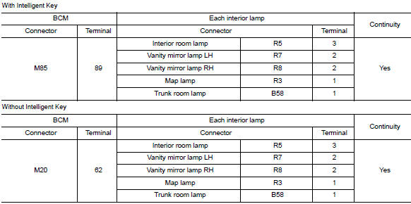
Is the inspection result normal? Yes >> go to 3.
No >> repair or replace the harness or connector.
3.Check battery saver output/power supply short circuit
Check continuity between BCM connector and ground.
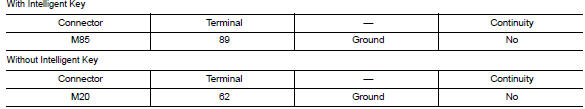
Is the inspection result normal? YES >> Check that each interior room lamp has no internal short circuit.
NO >> Repair or replace the harness or connector.
 Power supply and ground circuit
Bcm (body control system) (with intelligent key system)
BCM (BODY CONTROL SYSTEM) (WITH INTELLIGENT KEY SYSTEM) : Diagnosis Procedure
Regarding Wiring Diagram information, refer to BCS-51, "Wir ...
 Interior room lamp control circuit
Description
Controls each interior room lamp (ground side) by pwm signal.
Note:
Pwm signal control period is approximately 250 hz (in the gradual
brightening/dimming).
Component function check
...
Other materials:
P1800 Intake manifold tuning valve
DTC Logic
DTC DETECTION LOGIC
DTC No.
CONSULT screen terms
(Trouble diagnosis content)
DTC detecting condition
Possible cause
P1800
VIAS S/V-1
(Variable intake air system control
solenoid valve-1)
An excessively low or high voltage signal
is sent to ECM t ...
Front door
Door assembly
Door assembly : removal and installation
CAUTION:
Use two people when removing or installing the front door assembly
due to its heavy weight.
When removing and installing front door assembly, support front
door using a suitable tool.
Do not use air tools or electric to ...
Unit disassembly and assembly
Front coil spring and strut
Exploded View
Piston rod lock nut
Strut mount insulator
Strut mount bearing
Bound bumper
Coil spring
Lower rubber seat
Strut
Steering knuckle
Front
Disassembly and Assembly
DISASSEMBLY
CAUTION:
Do not damage the piston rod when removing comp ...
