Nissan Sentra Service Manual: Power supply and ground circuit
Bcm (body control system) (with intelligent key system)
BCM (BODY CONTROL SYSTEM) (WITH INTELLIGENT KEY SYSTEM) : Diagnosis Procedure
Regarding Wiring Diagram information, refer to BCS-51, "Wiring Diagram".
1.CHECK FUSES AND FUSIBLE LINK
Check that the following fuses and fusible link are not blown.
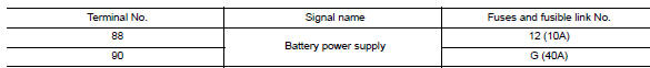
Is the fuse blown? YES >> Replace the blown fuse or fusible link after repairing the affected circuit.
NO >> GO TO 2.
2.Check power supply circuit
- Disconnect BCM connector M85.
- Check voltage between BCM connector M85 and ground.
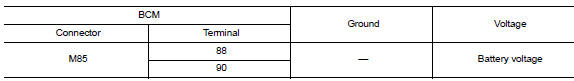
Is the inspection result normal? Yes >> go to 3.
No >> repair harness or connector.
3.Check ground circuit
Check continuity between bcm connector m85 and ground.
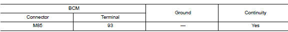
Is the inspection result normal? YES >> Inspection End.
NO >> Repair harness or connector.
Bcm (body control system) (without intelligent key system)
BCM (BODY CONTROL SYSTEM) (WITHOUT INTELLIGENT KEY SYSTEM) : Diagnosis Procedure
Regarding Wiring Diagram information, refer to BCS-111, "Wiring Diagram".
1.Check fuses and fusible link
Check that the following fuses and fusible link are not blown.
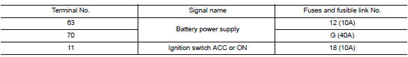
Is the fuse blown? Yes >> replace the blown fuse or fusible link after repairing the affected circuit.
No >> go to 2.
2.Check power supply circuit
- Turn ignition switch OFF.
- Disconnect bcm connectors.
- Check voltage between bcm connector and ground.
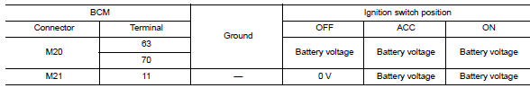
Is the inspection result normal? YES >> GO TO 3.
NO >> Repair harness or connector.
Is the inspection result normal? Yes >> go to 3.
No >> repair harness or connector.
3.Check ground circuit
Check continuity between bcm connector and ground.
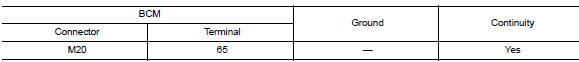
Is the inspection result normal? YES >> Inspection End.
NO >> Repair harness or connector.

 Battery saver output/power supply circuit
Description
Provides the battery saver output/power supply. Also cuts the power supply
when the interior lamp battery
saver is activated.
Component function check
1.Check battery saver output/po ...
Other materials:
Exterior lighting system symptoms
Symptom Table
Caution:
Perform the self-diagnosis with consult before the symptom diagnosis.
Perform the trouble diagnosis
if any dtc is detected.
Normal operating condition
Description
Auto light system
The auto light system may not turn the headlamp ON/OFF immediately after
pass ...
Both doors mirror defogger don’t operate but rear window defogger operates
Diagnosis procedure
Regarding Wiring Diagram information, refer to DEF-20, "Wiring Diagram".
1. Check door mirror defogger fuse
Check if the following fuse in fuse block (J/B) is blown.
Is the inspection result normal?
Yes >> go to 2.
No >> replace the blown fuse af ...
Removal and installation
Audio unit
Exploded view
Audio unit
Audio unit bracket (LH)
Audio unit bracket (rh)
Removal and installation
Removal
Disconnect the negative battery terminal. Refer to pg-50, "removal and
installation (battery)".
Remove cluster lid c lower. Refer to ip-20, "re ...
