Nissan Sentra Service Manual: C1116 Stop lamp switch
DTC Logic
DTC DETECTION LOGIC
| DTC | Display item | Malfunction detected condition | Possible cause |
| C1116 | STOP LAMP SW | When stop lamp switch circuit is open. |
|
DTC CONFIRMATION PROCEDURE
1.Check self-diagnosis results
Check the self-diagnosis results.
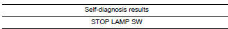
Is above displayed on the self-diagnosis display? Yes >> proceed to diagnosis procedure. Refer to brc-70, "diagnosis procedure".
No >> inspection end.
Diagnosis Procedure
Regarding wiring diagram information, refer to brc-44, "wiring diagram".
1.Connector inspection
-
Disconnect stop lamp switch connector and abs actuator and electric unit (control unit) connector.
-
Check terminals for deformation, disconnection, looseness or damage.
Is the inspection result normal? Yes >> go to 2
No >> repair or replace as necessary.
2.Check stop lamp switch circuit
-
Connect stop lamp switch connector.
-
Check voltage between abs actuator and electric unit (control unit) connector e33 terminal 30 and ground.
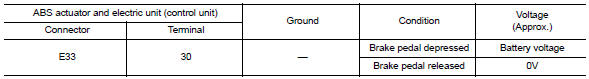
Is the inspection result normal? Yes >> replace abs actuator and electric unit (control unit). Refer to brc-110, "removal and installation".
No >> go to 3
3.Check stop lamp switch circuit for open
-
Disconnect stop lamp switch connector.
-
Check continuity between abs actuator and electric unit (control unit) connector e33 terminal 30 and stop lamp switch connector e60 terminal 2.
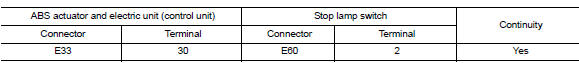
Is the inspection result normal? Yes >> go to 4.
No >> repair or replace as necessary.
4.Check stop lamp switch circuit for short
Check continuity between abs actuator and electric unit (control unit) connector e33 terminal 30 and ground.
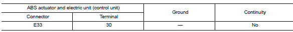
Is the inspection result normal? Yes >> replace stop lamp switch. Refer to br-22, "exploded view" no >> repair harness or connectors.
 C1115 ABS Sensor [abnormal signal]
DTC Logic
DTC DETECTION LOGIC
DTC
Display Item
Malfunction detected condition
Possible causes
C1115
ABS SENSOR
[ABNORMAL SIGNAL]
When difference in wheel speed betw ...
 C1120, C1122, C1124, C1126 ABS In valve system
DTC Logic
Dtc detection logic
DTC
Display Item
Malfunction detected condition
Possible causes
C1120
FR LH IN ABS SOL
When a malfunction is detected in front LH ABS IN
...
Other materials:
Driver side door mirror defogger
Description
Heats the heating wire with the power supply from the rear window defogger
relay to prevent the door mirror
from fogging up.
Component Function Check
Check that heating wire of door mirror defogger lh is heated when turning the
rear window defogger switch
on.
Is the inspect ...
Front seat
Driver side
DRIVER SIDE : Exploded View
Driver side
Headrest
Headrest holder (locked)
Headrest holder (free)
Seatback silencer
Seatback trim
Seatback pad
Seat belt buckle
Seat cushion outer finisher (RH)
Slide cover (RH)
Seat cushion inner finisher (RH)
Recline mech ...
Diagnosis system (ipdm e/r) (without intelligent key system)
Diagnosis Description
AUTO ACTIVE TEST
Description
In auto active test, the IPDM E/R sends a drive signal to the following
systems to check their operation.
Front wiper (LO, HI)
Parking lamp
License plate lamp
Tail lamp
Front fog lamp (if equipped)
Headlamp (LO, HI)
A/C compres ...
