Nissan Sentra Service Manual: C1120, C1122, C1124, C1126 ABS In valve system
DTC Logic
Dtc detection logic
| DTC | Display Item | Malfunction detected condition | Possible causes |
| C1120 | FR LH IN ABS SOL | When a malfunction is detected in front LH ABS IN valve. |
|
| C1122 | FR RH IN ABS SOL | When a malfunction is detected in front RH ABS IN valve. | |
| C1124 | RR LH IN ABS SOL | When a malfunction is detected in rear LH ABS IN valve. | |
| C1126 | RR RH IN ABS SOL | When a malfunction is detected in rear RH ABS IN valve. |
DTC CONFIRMATION PROCEDURE
1.CHECK SELF DIAGNOSTIC RESULT
 With CONSULT
-
Turn ignition switch ON.
-
Perform self diagnostic result.
Is DTC C1120, C1122, C1124 or C1126 detected? YES >> Proceed to diagnosis procedure. Refer to BRC-72, "Diagnosis Procedure".
NO >> Inspection End.
Diagnosis Procedure
Regarding Wiring Diagram information, refer to BRC-44, "Wiring Diagram".
1.CONNECTOR INSPECTION
-
Turn ignition switch OFF.
-
Disconnect ABS actuator and electric unit (control unit) connector.
-
Check connector and terminals for deformation, disconnection, looseness or damage.
Is the inspection result normal? YES >> GO TO 2.
NO >> Repair or replace as necessary.
2.Check ABS Actuator and electric unit (control unit) battery power supply
Check voltage between ABS actuator and electric unit (control unit) connector E33 terminal 25 and ground.
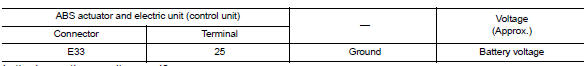
Is the inspection result normal? YES >> GO TO 3.
NO >> Repair or replace malfunctioning components.
3.Check ABS actuator and electric unit (control unit) ground circuit
Check continuity between ABS actuator and electric unit (control unit) connector E33 terminals 13, 38 and ground.
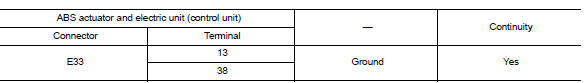
Is the inspection result normal? YES >> Replace ABS actuator and electric unit (control unit). Refer to BRC-110, "Removal and Installation".
NO >> Repair or replace malfunctioning components.
 C1116 Stop lamp switch
DTC Logic
DTC DETECTION LOGIC
DTC
Display item
Malfunction detected condition
Possible cause
C1116
STOP LAMP SW
When stop lamp switch circuit is open.
Harn ...
 C1121, C1123, C1125, C1127 ABS OUT Valve system
DTC Logic
DTC DETECTION LOGIC
DTC DETECTION LOGIC
Display Item
Malfunction detected condition
Possible causes
C1121
FR LH OUT ABS SOL
When a malfunction is detected i ...
Other materials:
How to set srt code
Description
OUTLINE
In order to set all SRTs, the self-diagnoses as in the “SRT ITEM” table must
have been performed at least
once. Each diagnosis may require actual driving for a long period of time under
various conditions.
SRT ITEM
The table below shows required self-diagnostic ...
Diagnosis system (bcm) (with intelligent
key system)
Common item
Common item : consult function (bcm -
common item)
APPLICATION ITEM
CONSULT performs the following functions via CAN communication with BCM.
Direct Diagnostic Mode
Description
ECU identification
The BCM part number is displayed.
Self Diagnostic Result
...
Dtc/circuit diagnosis
Eco mode switch
Component function check
1. Check eco mode switch operation
Turn ignition switch on.
Check ECO mode indicator lamp turns ON/OFF on combination meter when
turn ECO mode switch ON/
OFF.
Is the inspection result normal?
YES >> GO TO 2.
NO >> Proceed to DM ...
