Nissan Sentra Service Manual: Basic inspection
Diagnosis and repair work flow
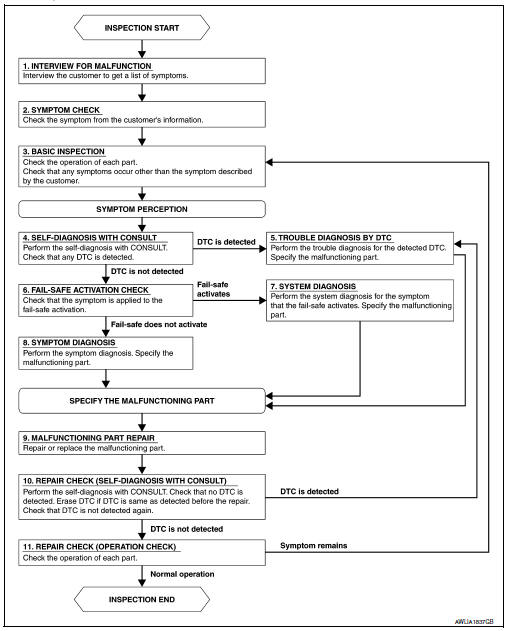
Work flow
OVERALL SEQUENCE
DETAILED FLOW
1.INTERVIEW FOR MALFUNCTION
Find out what the customer's concerns are.
>> GO TO 2
2.SYMPTOM CHECK
Verify the symptom from the customer's information.
>> GO TO 3
3.BASIC INSPECTION
Check the operation of each part. Check that any concerns occur other than those mentioned in the customer interview.
>> GO TO 4
4.SELF-DIAGNOSIS WITH CONSULT
Perform the self diagnosis with CONSULT. Check that any DTC is detected.
Is any DTC detected? YES >> GO TO 5
NO >> GO TO 6
5.TROUBLE DIAGNOSIS BY DTC
Perform the trouble diagnosis for the detected DTC. Specify the malfunctioning part.
>> GO TO 9
6.FAIL-SAFE ACTIVATION CHECK
Determine if the customer's concern is related to fail-safe activation.
Does the fail-safe activate? YES >> GO TO 7
NO >> GO TO 8
7.SYSTEM DIAGNOSIS
Perform the system diagnosis for the system in which the fail-safe activates. Specify the malfunctioning part.
>> GO TO 9
8.SYMPTOM DIAGNOSIS
Perform the symptom diagnosis. Specify the malfunctioning part.
>> GO TO 9
9.MALFUNCTION PART REPAIR
Repair or replace the malfunctioning part.
>> GO TO 10
10.REPAIR CHECK (SELF-DIAGNOSIS WITH CONSULT)
Perform the self diagnosis with CONSULT. Verify that no DTCs are detected. Erase all DTCs detected prior to the repair. Verify that DTC is not detected again.
Is any DTC detected? YES >> GO TO 5
NO >> GO TO 11
11.REPAIR CHECK (OPERATION CHECK)
Check the operation of each part.
Does it operate normally?
YES >> Inspection End.
NO >> GO TO 3
 Wiring diagram
Headlamp
Wiring diagram
Daytime light system
Wiring diagram
Auto light system
Wiring diagram
Front fog lamp
Wiring diagram
...

Other materials:
General Precautions
Always use a 12 volt battery as power source.
Do not attempt to disconnect battery cables while engine is
running.
Before connecting or disconnecting the ECM harness connector,
turn ignition switch OFF and disconnect negative battery
cable. Failure to do so may damage the ECM because
...
Removal and installation
Ecm
Exploded View
ECM bracket
ECM
Engine mounting insulator bracket
Removal and Installation
CAUTION:
Perform ADDITIONAL SERVICE WHEN REPLACING ECM. Refer to EC-135, "Work
Procedure".
REMOVAL
Remove battery. Refer to PG-50, "Removal and Installation (Battery)& ...
S connector circuit
Description
The starter motor magnetic switch is supplied with power when the ignition
switch is turned to the START position
while the selector lever is in the P (Park) or N (Neutral) position (CVT Models)
or the clutch pedal is
depressed (M/T Models).
Diagnosis Procedure
Regarding Wiring ...
