Nissan Sentra Service Manual: Clutch pedal
Exploded View
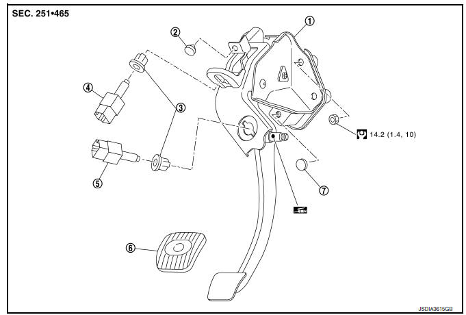
- Clutch pedal
- Stopper rubber
- Clip
- Clutch interlock switch (if equipped)
- Clutch pedal position switch (if equipped)
- Pedal pad
- Pedal stopper rubber
Removal and Installation
REMOVAL
- Remove instrument lower panel LH. Refer to IP-21, "Removal and Installation".
- Disconnect the harness connector from the clutch pedal position switch (if equipped).
- Disconnect the harness connector from the clutch interlock switch (if equipped).
- Disconnect clip of harness from clutch pedal.
- Remove clutch master cylinder rod end from clutch pedal.
- Remove clutch pedal position switch and clip from clutch pedal (if equipped).
- Remove clutch interlock switch and clip from clutch pedal (if equipped).
- Remove clutch pedal from the vehicle
- Remove pedal pad from clutch pedal.
- Remove stopper rubber and pedal stopper rubber from clutch pedal, using a suitable remover.
INSTALLATION
Installation is in the reverse order of removal.
CAUTION:
After applying recommended grease, press clutch master cylinder rod end into clutch pedal until it stops.
Inspection and Adjustment
INSPECTION AFTER REMOVAL
- Check clutch pedal for bend, damage, or a cracked weld. If bend, damage, or a cracked weld is found, replace clutch pedal.
- Check pedal stopper rubber (if equipped). If damage or deformation is
found, replace pedal stopper rubber.
(if equipped)
- Check stopper rubber. If damage or deformation is found, replace stopper rubber.
- Check pedal pad. If wear or damage is found, replace pedal pad.
INSPECTION AFTER INSTALLATION
- Check the height of clutch pedal. Refer to CL-5, "Inspection and Adjustment".
- Check the clutch interlock switch position (if equipped). Refer to CL-5, "Inspection and Adjustment".
- Check the clutch pedal position switch position (if equipped). Refer to CL-5, "Inspection and Adjustment".
ADJUSTMENT AFTER INSTALLATION
- Adjust the clutch interlock switch position (if equipped). Refer to CL-5, "Inspection and Adjustment".
- Adjust the clutch pedal position switch position (if equipped). Refer to CL-5, "Inspection and Adjustment".

 Clutch master cylinder
Exploded View
Reservoir hose
Reservoir tank
Clutch master cylinder
Removal and Installation
REMOVAL
CAUTION:
Keep painted surface on the body or other parts free of clutch
flui ...
Other materials:
Tcm branch line circuit
Diagnosis Procedure
1.Check connector
Turn the ignition switch off.
Disconnect the battery cable from the negative terminal.
Check the following terminals and connectors for damage, bend and loose
connection (unit side and connector
side).
TCM
Harness connector f50
Harness co ...
P2101 Electric throttle control function
DTC Logic
DTC DETECTION LOGIC
NOTE:
If DTC P2101 is displayed with DTC P2100, first perform the trouble
diagnosis for DTC P2100. Refer
to EC-423, "DTC Logic".
If DTC P2101 is displayed with DTC P2119, first perform the trouble
diagnosis for DTC P2119. Refer
to EC-430, &qu ...
U1000 Can comm circuit
Description
CAN (Controller Area Network) is a serial communication line for real-time
application. It is an on-vehicle multiplex
communication line with high data communication speed and excellent malfunction
detection ability.
Many electronic control units are equipped onto a vehicle, an ...
