Nissan Sentra Service Manual: Wiring diagram
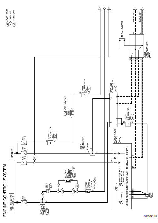
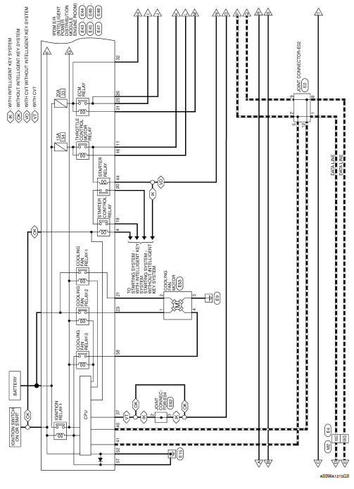
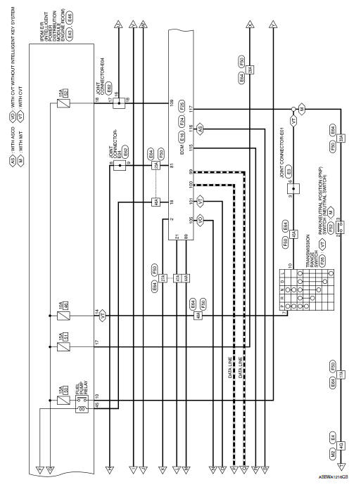
Engine control system
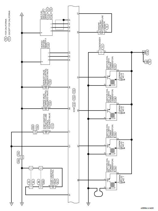
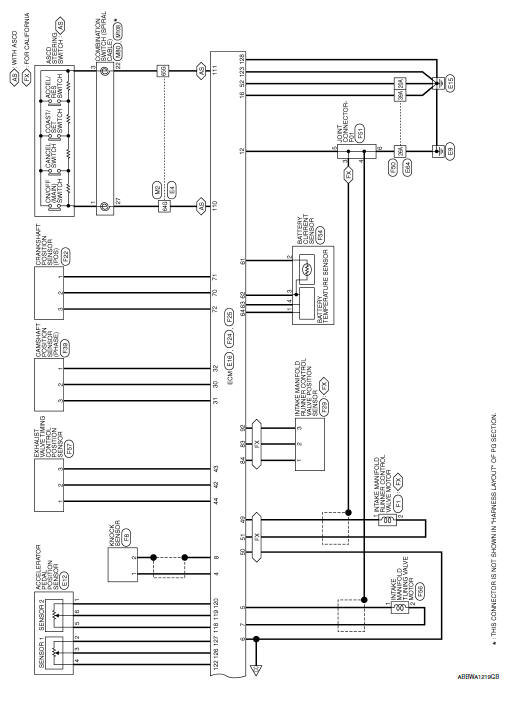
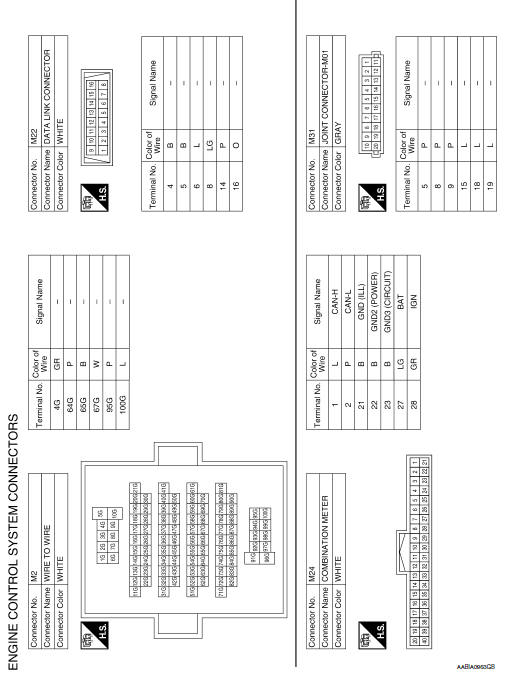
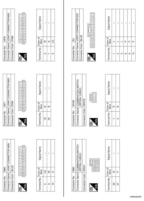
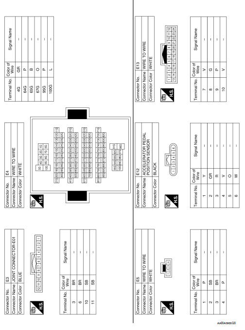
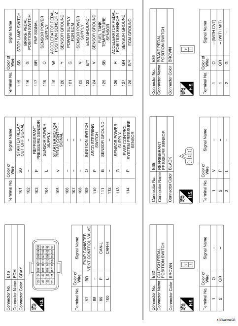
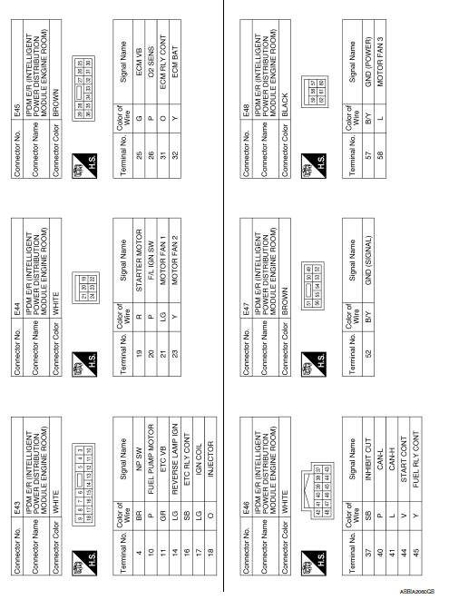
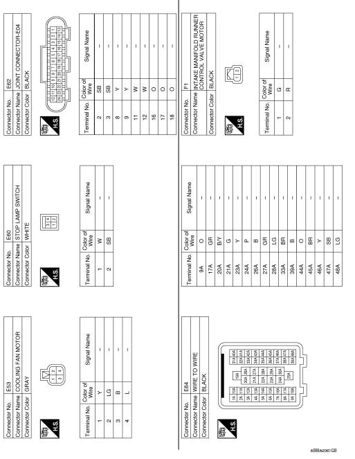
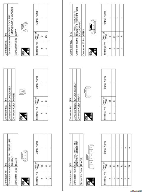
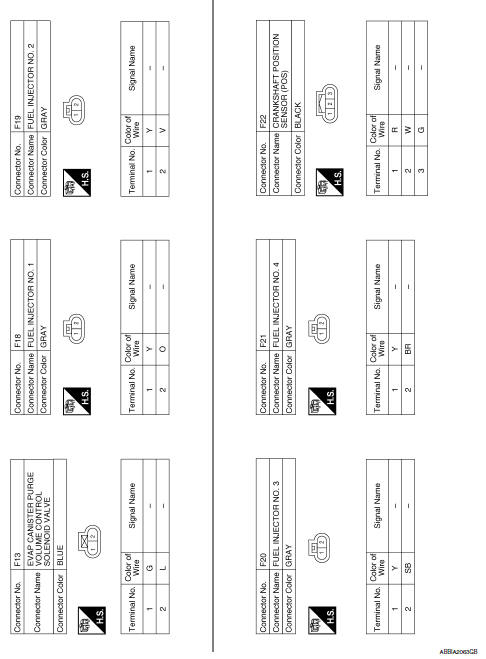
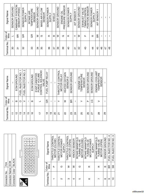
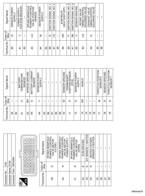
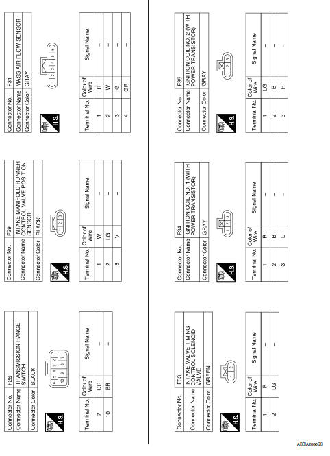
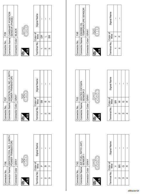
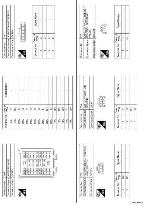
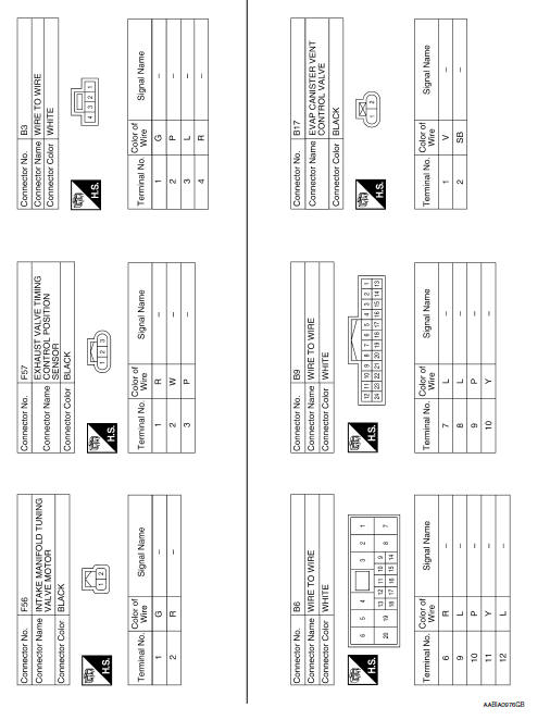
Wiring Diagram
 Ecu diagnosis information
ECM
Reference Value
VALUES ON THE DIAGNOSIS TOOL
NOTE:
The following table includes information (items) inapplicable to this
vehicle. For information (items) applicable
to this vehicle, re ...
 Basic inspection
...
Other materials:
Ecu diagnosis information
Bcm
Reference value
NOTE:
The Signal Tech II Tool (J-50190) can be used to perform the following
functions. Refer to the Signal Tech II
User Guide for additional information.
Activate and display TPMS transmitter IDs
Display tire pressure reported by the TPMS transmitter
Read TPMS DTC ...
B0010, B0011 Passenger airbag module
Description
DTC B0010, B0011 PASSENGER AIR BAG MODULE
The passenger air bag module is dual stage and is wired to the air bag
diagnosis sensor unit. The air bag diagnosis
sensor unit will monitor for opens and shorts in detected lines to the passenger
air bag module.
PART LOCATION
Refer to S ...
C1164, C1165, C1166, C1167 CV/SV System
DTC Logic
Dtc detection logic
DTC
Display Item
Malfunction detected condition
Possible causes
C1164
CV 1
When a malfunction is detected in cut valve 1.
Harness or connector
ABS actuator and electric unit
(control unit)
Fusible link
Battery ...
