Nissan Sentra Service Manual: Wiring diagram
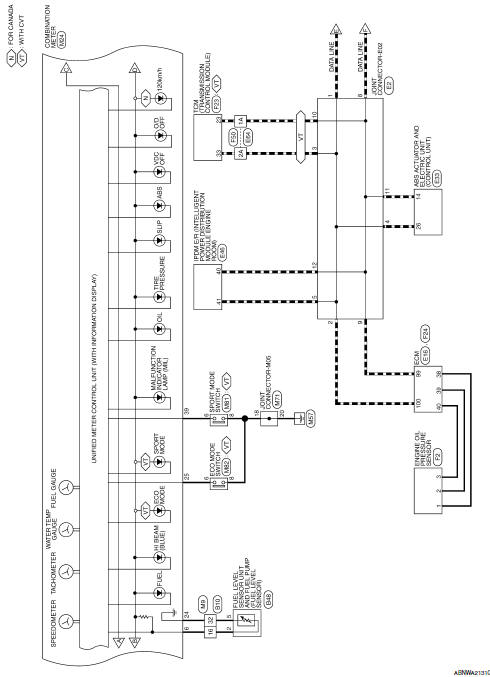
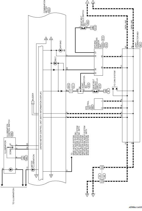
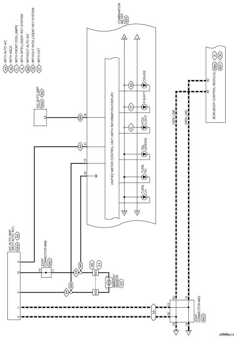
Meter system
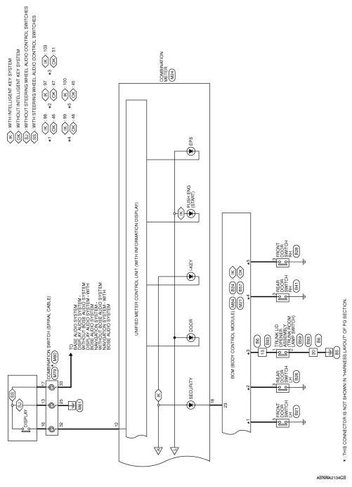
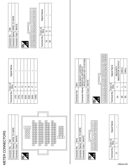
Wiring diagram
Compass
Wiring diagram
 Bcm (body control module)
List of ECU Reference
...
 Basic inspection
Diagnosis and repair workflow
Work flow
Overall sequence
Detailed flow
1.Obtain information about symptom
Interview the customer to obtain as much information as possible about the
conditio ...
Other materials:
License lamp finisher
Exploded view
Rear view camera
Trunk lid opener request switch
License lamp finisher
Clip
Pawl
Removal and installation
Remove trunk lid finisher. Refer to INT-45, "Removal and Installation".
Disconnect the harness connector (A) from trunk lid opener
request swit ...
Primary speed sensor
Exploded View
Transaxle assembly
O-ring
Primary speed sensor
: Always replace after every
disassembly.
: N m (kg-m, in-lb)
: Genuine NISSAN CVT Fluid NS-3
Removal and Installation
REMOVAL
Disconnect the primary speed sensor connector.
Remove the primary speed sensor.
...
Power supply and ground circuit
WITH INTELLIGENT KEY SYSTEM
WITH INTELLIGENT KEY SYSTEM : Diagnosis Procedure
Regarding Wiring Diagram information, refer to BCS-51, "Wiring Diagram".
1.Check fuses and fusible link
Check that the following fuses and fusible link are not blown.
Is the fuse blown?
Yes >> r ...
