Nissan Sentra Service Manual: Basic inspection
Diagnosis and repair workflow
Work flow
Overall sequence
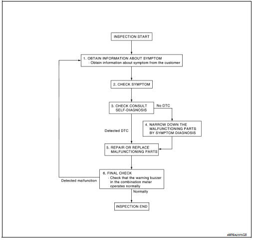
Detailed flow
1.Obtain information about symptom
Interview the customer to obtain as much information as possible about the conditions and environment under which the malfunction occurred.
>> GO TO 2.
2.Check symptom
- Check the symptom based on the information obtained from the customer.
- Check if any other malfunctions are present.
>> Go to 3.
3.Check consult self-diagnosis results
Connect consult and perform self-diagnosis. Refer to mwi-26, "dtc index".
Are self-diagnosis results normal? Yes >> go to 4.
No >> go to 5.
4.Narrow down malfunctioning parts by symptom diagnosis
Perform symptom diagnosis and narrow down the malfunctioning parts.
>> Go to 5.
5.Repair or replace malfunctioning parts
Repair or replace malfunctioning parts.
Note:
If dtc is displayed, erase dtc after repairing or replacing malfunctioning parts.
>> Go to 6.
6.Final check
Check that the warning buzzer in the combination meter operates normally.
Does it operate normally? Yes >> inspection end.
No >> go to 1.
 Wiring diagram
Meter system
Wiring diagram
Compass
Wiring diagram
...

Other materials:
License plate lamp
Removal and Installation
REMOVAL
Remove the license lamp finisher. Refer to EXT-44, "Removal and
Installation".
Disconnect the harness connector (A) from the license plate
lamp (1).
Release pawl and remove.
: Pawl
INSTALLATION
Installation is in the reverse order of ...
Service Notice and Precautions for TPMS
WARNING:
Radio waves could adversely affect electric medical equipment. Those
who use a pacemaker should
contact the electric medical equipment manufacturer for the possible influences
before use.
Low tire pressure warning lamp blinks for 1 minute, then turns ON when
occurring any malfu ...
F.M.V.S.S./C.M.V.S.S. certification label
The Federal/Canadian Motor Vehicle Safety
Standard (F.M.V.S.S./C.M.V.S.S.) certification label
is affixed as shown. This label contains valuable
vehicle information, such as: Gross Vehicle
Weight Ratings (GVWR), Gross Axle Weight
Rating (GAWR), month and year of manufacture,
Vehicle Identi ...
