Nissan Sentra B18 (2020-2025) Service Manual: Wiper & Washer :: System Description
Component Parts. Front Wiper and Washer System. Front Wiper and Washer System
Component Parts Location
Component Parts Location
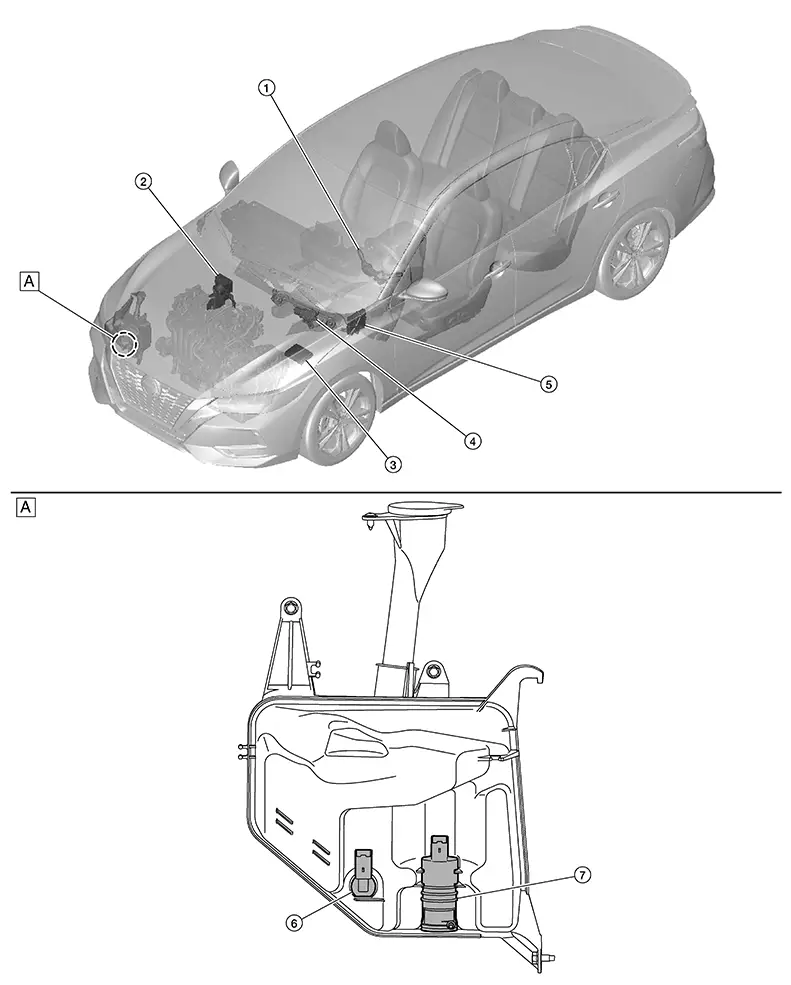
|
A. |
Right front of engine compartment (view with washer tank removed) |
|
No. |
Component |
Function |
|---|---|---|
|
1. |
Combination switch (wiper and washer switch) |
Inputs the combination switch (wiper and washer switch) signal to the BCM. Refer to Wiper and Washer Switch. |
|
2. |
ABS actuator and electric unit (control unit) [Anti-lock Braking System actuator and electric unit (control unit)] |
Inputs the Nissan Sentra vehicle speed signal via CAN communication. Refer to Component Parts Location for detailed component location. |
|
3. |
IPDM E/R (Intelligent Power Distribution Module Engine Room) |
Refer to System Description. |
|
4. |
Front wiper motor |
Refer to Front Wiper Motor. |
|
5. |
BCM (Body Control Module) |
Refer to System Description. |
|
6. |
Washer fluid level switch (if so equipped) |
Refer to Washer Fluid Level Switch. |
|
7. |
Front washer motor |
Refer to Front Washer Motor. |
Wiper and Washer Switch
Wiper and Washer Switch
-
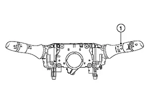
Wiper and washer switch (1) is integrated with the combination switch (wiper and washer switch).
-
The wiper switch transmits the wiper switch status signals to the BCM.
-
The BCM transmits the wiper switch status signal request to the IPDM E/R via CAN communication for wiper motor operation.
-
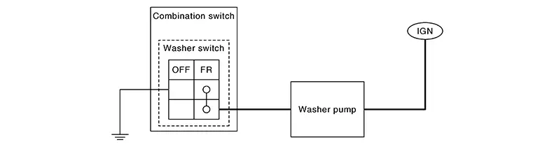
The washer switch supplies ignition power supply to the front washer motor to operate the washer pump.
-
The front washer motor is grounded through the combination switch (wiper and washer switch) while the washer switch is ON.
Front Wiper Motor
Front Wiper Motor
-
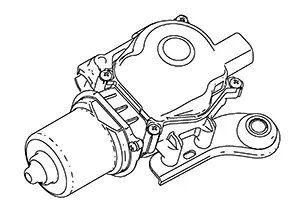
The front wiper motor is installed in the cowl on the linkage assembly.
-
Controls front wiper operation with IPDM E/R control.
-
Transmits front wiper stop position signal to the IPDM E/R.
-
When power is supplied to the HI terminal of the front wiper motor HI mode operates.
-
When power supply is supplied to the LO terminal of the front wiper motor LO operates.
-
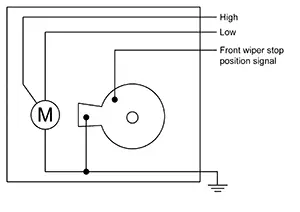
When the front wiper motor is at the stop position, two points of contact in the front wiper motor are connected, and the front wiper stop position signal is grounded.
-
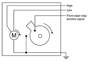
When the front wiper motor operates, two points of contact in the front wiper motor are not connected, and the front wiper stop position signal is not grounded.
-
The IPDM E/R detects the front wiper stop position signal from the front wiper motor to find out the front wiper motor position (stop position/except stop position).
Front Washer Motor
Front Washer Motor
-
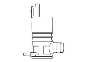
The front washer motor is installed on the washer tank assembly in the right front of the engine compartment.
-
Front washer motor operates the front washer.
-
Front washer motor spray washer fluid depending on the state of the washer switch.
Washer Fluid Level Switch
Washer Fluid Level Switch
-
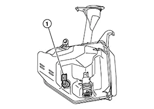
The washer fluid level switch 1 is installed on the washer tank assembly in the RH of the engine compartment.
-
Detects that washer fluid level is low and transmits washer level signal to combination meter.
System. System Description. System Description
System Description
SYSTEM DIAGRAM
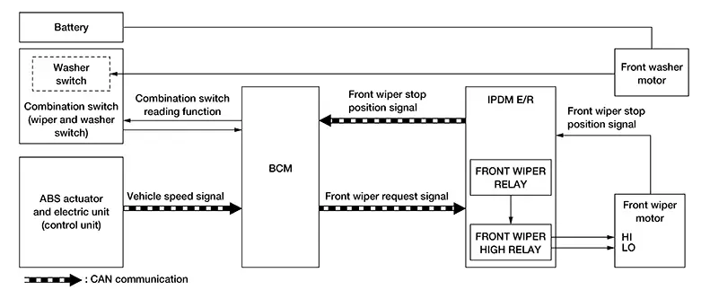
OUTLINE
The front wiper is controlled by each function of the BCM and IPDM E/R.
Control by BCM:
-
Combination switch reading function
-
Front wiper control function
Control by IPDM E/R:
-
Front wiper control function
-
Relay control function
INPUT SIGNAL AND OUTPUT SIGNAL
|
Signal name |
Input |
Output |
Description |
|---|---|---|---|
|
Combination switch (wiper and washer switch) |
Combination switch (wiper and washer switch) |
BCM |
Transmits the combination switch (wiper and washer switch) signal for front wiper and washer system operation to the BCM. |
|
Nissan Sentra Vehicle speed signal |
ABS actuator and electric unit (control unit) |
BCM (CAN) |
Transmits the Nissan Sentra vehicle speed signal via CAN communication. |
|
Front wiper request signal |
BCM |
IPDM E/R (CAN) |
Transmits the front wiper request signal via CAN communication. |
|
Front wiper stop position signal |
Front wiper motor |
IPDM E/R |
Inputs the front wiper motor stop position signal to the IPDM E/R. |
|
Front wiper stop position signal |
IPDM E/R |
BCM (CAN) |
Transmits the front wiper motor stop position signal via CAN communication. |
FRONT WIPER BASIC OPERATION
-
The BCM detects the combination switch (wiper and washer switch) condition by the combination switch reading function.
-
The BCM transmits the front wiper request signal to the IPDM E/R via CAN communication depending on each operating condition of the front wiper.
-
The IPDM E/R turns ON/OFF the integrated front wiper relay and the front wiper high relay according to the front wiper request signal. The IPDM E/R provides the power supply to operate front wiper HI/LO operation.
FRONT WIPER LO OPERATION
-
The BCM transmits the front wiper request signal (LOW) to the IPDM E/R via CAN communication according to the front wiper LO operating condition.
Front wiper LO operating condition:
-
Ignition switch ON
-
Front wiper switch LO or front wiper switch MIST (while pressing)
-
-
IPDM E/R turns ON the integrated front wiper relay according to the front wiper request signal (LOW).
FRONT WIPER HI OPERATION
-
BCM transmits the front wiper request signal (HIGH) to IPDM E/R via CAN communication according to the front wiper HI operating condition.
Front wiper HI operating condition:
-
Ignition switch ON
-
Front wiper switch HI
-
-
The IPDM E/R turns ON the integrated front wiper relay and the front wiper high relay according to the front wiper request signal (HIGH).
FRONT WIPER INT OPERATION
-
The BCM transmits the front wiper request signal (LOW) to the IPDM E/R via CAN communication depending on the front wiper INT operating condition and intermittent operation delay interval according to the wiper volume dial position.
Front wiper INT operating condition:
-
Ignition switch ON
-
Front wiper switch INT
-
-
The IPDM E/R turns ON the integrated front wiper relay so that the front wiper is operated only once according to the front wiper request signal (LOW) and front wiper request signal (RETURN).
-
The BCM detects stop position/except stop position of the front wiper motor according to the front wiper stop position signal received from the IPDM E/R via CAN communication.
-
The BCM transmits the front wiper request signal (LOW) again after the intermittent operation delay interval.

The front wiper INT operation setting of the linked or not linked with Nissan Sentra vehicle speed can be changed by the combination meter setting.
Front wiper intermittent operation with Nissan Sentra vehicle speed
-
The BCM calculates the intermittent operation delay interval from the following:
-
Nissan Sentra Vehicle speed signal
-
Wiper volume dial position
-
|
Wiper volume dial position |
Intermittent operation interval |
Nissan Sentra Vehicle speed |
|||
|---|---|---|---|---|---|
|
0 – 18.6 MPH (0 – 30 km/h) |
15.5 – 37.3 MPH (25 – 60 km/h) |
34.2 – 65.2 MPH (55 – 105 km/h) |
62.1 MPH (100 km/h) or more |
||
|
1 |
Long ↑ ↓ Short |
21.0 |
18.9 |
15.8 |
12.6 |
|
2 |
11.2 |
10.1 |
8.4 |
6.7 |
|
|
3 |
5.6 |
5.0 |
4.2 |
3.4 |
|
|
4 |
2.8 |
2.5 |
2.1 |
1.7 |
|
|
5 |
1.4 |
1.3 |
1.1 |
0.8 |
|
FRONT WIPER AUTO STOP OPERATION
-
The BCM transmits the front wiper request signal (RETURN) to the IPDM E/R via CAN communication when the front wiper switch is turned OFF.
-
The IPDM E/R detects the front wiper stop position signal from the front wiper motor to find out the front wiper motor position (stop position/except stop position).
-
When the IPDM E/R receives the front wiper request signal (RETURN) from the BCM and the front wiper motor position is not in the stop position, the IPDM E/R turns ON the front wiper relay until the front wiper motor returns to the stop position.
-
When the front wiper motor returns to the stop position, the IPDM E/R transmits the front wiper status signal to the BCM via CAN communication.
-
When the BCM receives the front wiper status signal from the IPDM E/R, the BCM transmits the front wiper request signal (STOP) to the IPDM E/R via CAN communication.
FRONT WIPER OPERATION LINKED WITH WASHER
-
The BCM transmits the front wiper request signal (LOW) to the IPDM E/R via CAN communication according to the washer linked operating condition of the front wiper.
-
The BCM transmits the front wiper request signal (LOW) so that the front wiper operates approximately 2 times when the front washer switch OFF is detected.
Washer linked operating condition of front wiper:
-
Ignition switch ON
-
Front washer switch ON (0.4 second or more)
-
-
The IPDM E/R turns ON the integrated front wiper relay according to the front wiper request signal (LOW).
-
The washer pump is grounded through the combination switch with the front washer switch ON.
Diagnosis System (bcm). Common Item
Consult Function (bcm - Common Item)
CONSULT Function (BCM - COMMON ITEM)
|
BCM |
Refer to CONSULT Function (BCM - COMMON ITEM). |
Wiper
Consult Function (bcm - Wiper)
CONSULT Function (BCM - WIPER)
|
BCM |
Refer to CONSULT Function (BCM - WIPER). |
Diagnosis System (ipdm E/r). Consult Function (ipdm E/r). Consult Function (ipdm E/r)
CONSULT Function (IPDM E/R)
|
IPDM E/R |
Refer to CONSULT Function (IPDM E/R). |
Other materials:
C161a-83 Abs System
Dtc Description
DTC Description
DTC DETECTION LOGIC
DTC No.
CONSULT screen terms
(Trouble diagnosis content)
DTC detection condition
...
B203f-14 Outside Antenna
Dtc Description
DTC Description
DTC DETECTION LOGIC
DTC No.
CONSULT screen items
(Trouble diagnosis
content)
DTC detecting condition
...
Diagnosis System (distance Sensor)
Consult Function (laser/radar)
CONSULT Function (LASER/RADAR)
APPLICATION ITEMS
CONSULT performs the following functions via CAN communication
with ADAS control unit 2 and the communication with distance sensor.
...