Nissan Sentra Service Manual: Trunk room trim
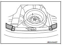
Exploded View
- Trunk floor trim
- Trunk front floor spacer (LH)
- Trunk side finisher (LH)
- Reflector box assembly*
- Trunk rear plate
- Trunk side finisher (RH)
- Trunk front floor spacer (RH)
 Clip
Clip
 Pawl
Pawl
Trunk rear plate
TRUNK REAR PLATE : Removal and Installation
REMOVAL
- Remove trunk floor trim.
- Remove clips (A).
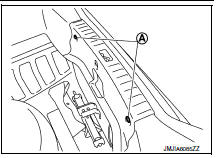
- Release trunk rear plate pawls as shown.
 Pawl
Pawl
- Remove trunk rear plate.
INSTALLATION
Installation is in the reverse order of removal.
CAUTION:
When installing, check that clips and pawls are accurately aligned with the holes on body panel, then press in.
Trunk side finisher
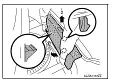
TRUNK SIDE FINISHER : Removal and Installation
REMOVAL
- Remove trunk rear plate. Refer to INT-42, "TRUNK REAR PLATE : Removal and Installation".
- Apply protective tape (A) to protect the component from damage as shown.
- Release trunk side finisher clips using a suitable tool (A).
 : Clip
- Remove trunk side finisher clips (A) and the trunk side finisher (1).
 : Clip
INSTALLATION
Installation is in the reverse order of removal.
CAUTION:
- Insert rear end of trunk side finisher into trunk weather strip.
- When installing, check that clips are accurately aligned with the holes on body panel, then press in.
 Headlining
Exploded View
STANDARD ROOF
Headlining
Assist grip
Map lamp bracket
Sun visor (RH)
Sun visor cover
Sun visor holder
Map lamp
Sun visor (LH)
Interior room lamp
Assist grip cap ...
 Trunk lid trim
Exploded View
Trunk lid finisher
Front
Removal and Installation
REMOVAL
Remove trunk lid finisher clips (A) and trunk lid finisher.
INSTALLATION
Installation is in the reverse ord ...
Other materials:
ECU diagnosis information
A/C AUTO AMP
Reference Value
VALUES ON THE DIAGNOSIS TOOL
TERMINAL LAYOUT
PHYSICAL VALUES
DTC Inspection Priority Chart
If some DTCs are displayed at the same time, perform inspections one by one
based on the following priority
chart.
DTC Index
*: Perform self ...
How to use the APPS – i button
For more information about the “SiriusXM Travel
Link”, and “SiriusXM Traffic” features, see the
separate Navigation System Owner’s Manual.
For more information about the “My Apps” key,
see “NissanConnect™ App Smartphone Integration”
in this section.
For more infor ...
A-bag branch line circuit
Diagnosis procedure
Warning:
Always observe the following items for preventing accidental
activation.
Before servicing, turn ignition switch off, disconnect battery
negative terminal, and wait 3 minutes
or more. (To discharge backup capacitor.)
Never use unspecified tester or other ...
